System for connecting a structural cable to a building work structure

a technology for connecting structural cables and building work structures, which is applied to cables for vehicles/pulleys, bridges, structural elements, etc., can solve the problems of not always easy to access and expensive installation

Inactive Publication Date: 2002-12-03
FREYSSINET INT STUP
View PDF12 Cites 19 Cited by
  • Summary
  • Abstract
  • Description
  • Claims
  • Application Information

AI Technical Summary

Benefits of technology

Each cable is tensioned between a constituent element 7 of the platform 1, for example beams of the upper part 2, and an anchoring block located on the sea bed 3, by means of connecting systems 10 which will be described hereinafter. Each cable is subjected to significant tensile loadings while at the same time having very good fatigue strength and exhibiting very good corrosion resistance.

Problems solved by technology

These systems are not always easy to access, which makes them expensive to install.

Method used


Image

  • System for connecting a structural cable to a building work structure
  • System for connecting a structural cable to a building work structure
  • System for connecting a structural cable to a building work structure

Examples


first embodiment

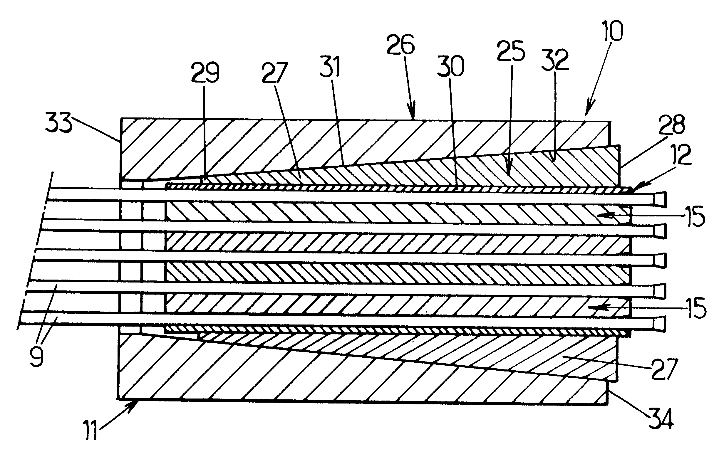
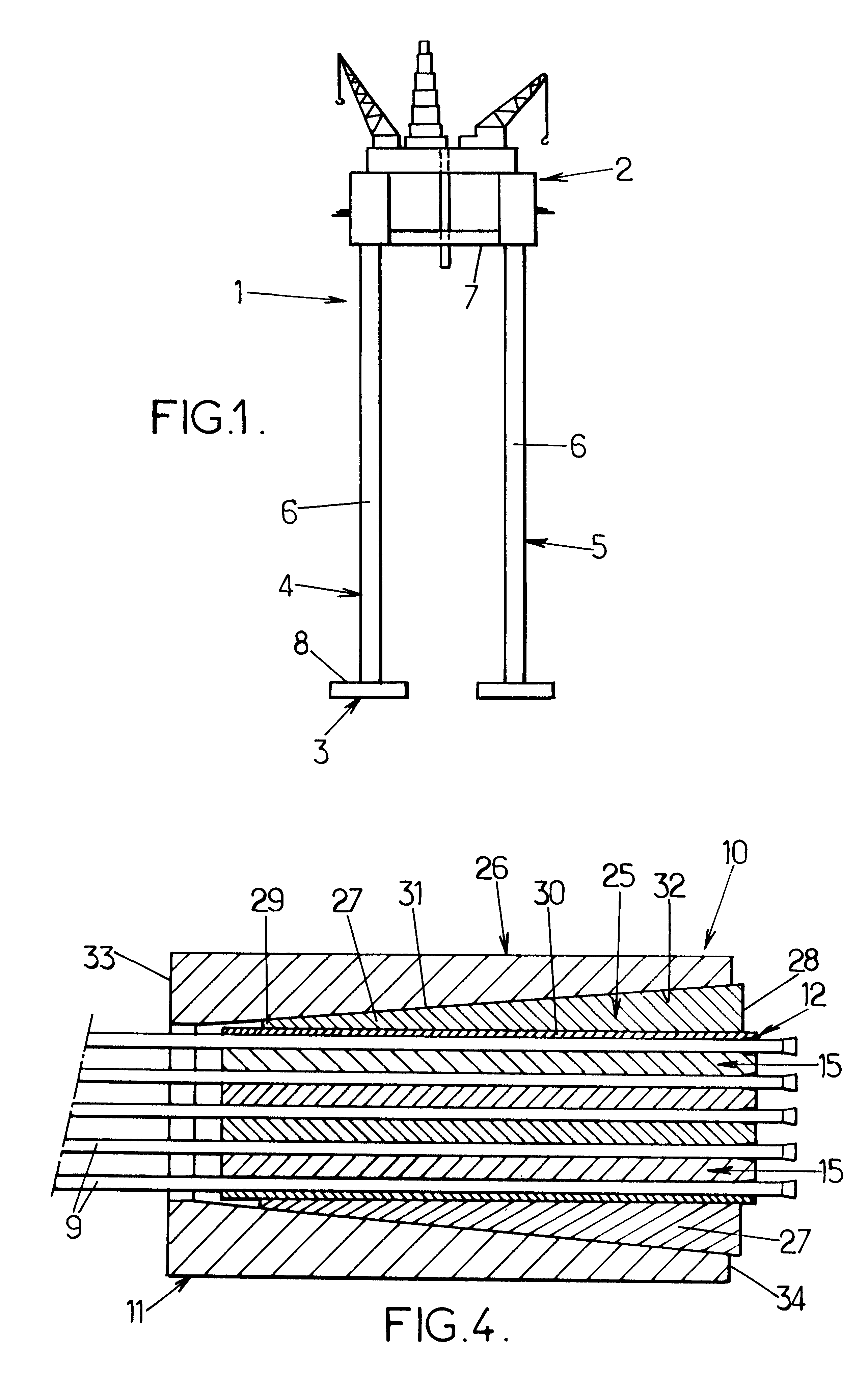
The transmitting device 12 consists, in the first embodiment, of a certain number of plates 15 between which the wires 9 are housed.

Each of the plates 15 is of roughly rectangular shape and has a top side 16, an underside 17 which is roughly flat, and longitudinal edges 18 which, taken along the thickness of the plate, are of curved shape so that the collection of plates 15, once superposed one on the other, form a cylinder on a circular base. Thus, each plate 15 forms a kind of longitudinal slide of a cylinder, which is thin in comparison with its length.

Each top side 16 and each underside 17 of the plates 15 has a channel 20. The cross section of the channels 20 is similar to half the cross section of the wires 9.

The channels 20 of a top side 16 of one plate 15 face the channels 20 of an underside 17 of the next plate 15. The channels 20 thus, in pairs, define passageways 21, the cross section of which complements that of the wires 9.

The plates 15 are made of a metallic material o...

second embodiment

In the second embodiment depicted in FIGS. 5 and 6, the connection system 50 differs from the previously described one only in the form of the load transmitting device 52, the other constituent elements are similar and bear identical numeral references.

The transmitting device 52 no longer occupies the entire interior volume of the cylinder defined by the keys 27 of the jaw assembly 25. This device consists of a number of metal sleevings 55, for example made of aluminum. The sleevings 55 are of an inside diameter roughly identical to the diameter of the wires 9 so that these wires are forced into the sleevings. The outside diameter of the sleevings is small by comparison with the inside diameter of the cylinder delimited by the keys 27.

The wires 9 are also bonded into the sleevings 55. These sleevings are made of a material with a low elastic limit, possessing a certain plasticity.

The way in which the connecting system 50 is mounted is roughly identical to the way in which the system...


PUM

PropertyMeasurementUnit
shapeaaaaaaaaaa
tensionaaaaaaaaaa
tensileaaaaaaaaaa

Abstract

A connecting system for connecting a cable including at least one wire for a building work structure and an element of the structure. The connecting system comprises a clamping device which is connected to the element of the structure, and a load transmitting device which transmits a clamping load of the clamping device to the cable and which houses the at least one wire of the cable. The at least one wire is bonded into the load transmitting device.

Description

The present invention relates to a connecting system for connecting a cable for a building work structure and an element of this structure, the cable comprising at least one wire.The present invention relates in particular to cables made up of a certain number of strands themselves combining several wires, which are stressed particularly in tension in building work structures Such as offshore platforms of the tension-leg type, or suspension or cable stayed bridges.DESCRIPTION OF RELATED ARTConnecting systems are needed to anchor the cables, for example, in the sea bed. These systems are not always easy to access, which makes them expensive to install.It is an object of the invention to provide a connecting system in which the wires are firmly anchored to withstand in particular tensile loadings and to do so using means which are simple, effective and inexpensive.To this end, according to the invention, a connecting system of the kind in question is essentially characterized in that ...

Claims


Application Information

Patent Timeline
Patent Type & Authority Patents(United States)
IPC IPC(8): E01D19/14E01D19/00E04C5/12E01D11/02E01D11/04E01D11/00E01D19/16E04B1/58
CPCE01D19/14E04C5/122E04C5/127Y10T24/3969Y10T24/3909Y10T24/3996
Inventor STUBLER, JEROMEGEFFROY, RENE-LOUIS
Owner FREYSSINET INT STUP
Why Eureka
Try Eureka