Butterfly valve

a technology of butterfly valve and guide parts, which is applied in the direction of valve operating means/release devices, mechanical equipment, etc., can solve the problems of affecting the operation of the valve, the construction of the guide parts is delicate, and the vacuum must be disadvantageously provided, so as to achieve the effect of less susceptible to malfunction, simple technique and long li

Inactive Publication Date: 2002-12-17
VAT HLDG AG
View PDF6 Cites 57 Cited by
  • Summary
  • Abstract
  • Description
  • Claims
  • Application Information

AI Technical Summary

Benefits of technology

It is an object of the invention to provide a butterfly valve in which the release of particles in the vacuum when the valve is actuated is reduced. A further object of the invention is to provide a butterfly valve in which a lubricating grease need not be used in the vacuum. It is another object of the invention to provide a butterfly valve having no parts moving relative to one another in the vacuum. It is a further object of the invention to provide a butterfly valve which is less susceptible to malfunction and which has a longer life. It is another object of the invention to provide a butterfly valve which can be manufactured using simple techniques and which is easy to service.
Accordingly, in a butterfly valve according to the invention, the link guide for generating the closing movement of the valve is located outside of the valve opening and also outside of the vacuum. Therefore, this guide can be constructed in a correspondingly robust manner without impairing the through-flow cross section of the valve in the opened state. Further, the lubrication of the link guide located outside of the vacuum does not present a problem. Further, in a butterfly valve according to the invention, other guide parts moving relative to one another can also be avoided in the vacuum. This minimizes the release of particles in the vacuum when opening and closing the valve. A vacuum valve according to the invention can also be designed for a long service life.
In a preferred embodiment example, the tilting axis of the valve rod is formed by a journal which penetrates the valve rod, this journal being mounted in a ball bearing surrounding the valve rod so that it can swivel about the longitudinal axis of the valve rod in this way. This results in a low-friction, durable rotating / tilting joint which has only slight play.

Problems solved by technology

A disadvantage in these known butterfly valves consists in that particles are released into the vacuum by the rolling and sliding movements of the joint ball in the housing and of the journal in the link during the adjustment of the valve.
Further, these parts which move relative to one another require lubrication, so that a lubricating grease must be disadvantageously provided in the vacuum.
In order that the free through-opening is as large as possible in the opened state of the valve, the links and the connection part with the journal must be constructed so as to be relatively small, so that the construction of these guide parts is delicate and comparatively prone to disturbance on the whole.
After prolonged use of the valve, these axial forces lead to increased friction on the ball relative to the seat.
This in turn causes an increase in axial forces and so on, so that the bearing and joint ball are ultimately destroyed and the valve is unusable.

Method used


Image

  • Butterfly valve
  • Butterfly valve
  • Butterfly valve

Examples


Embodiment Construction

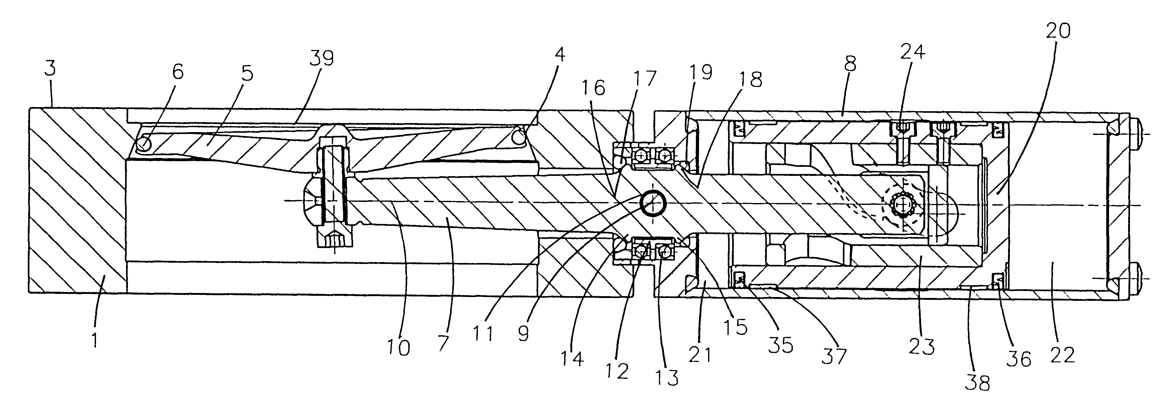
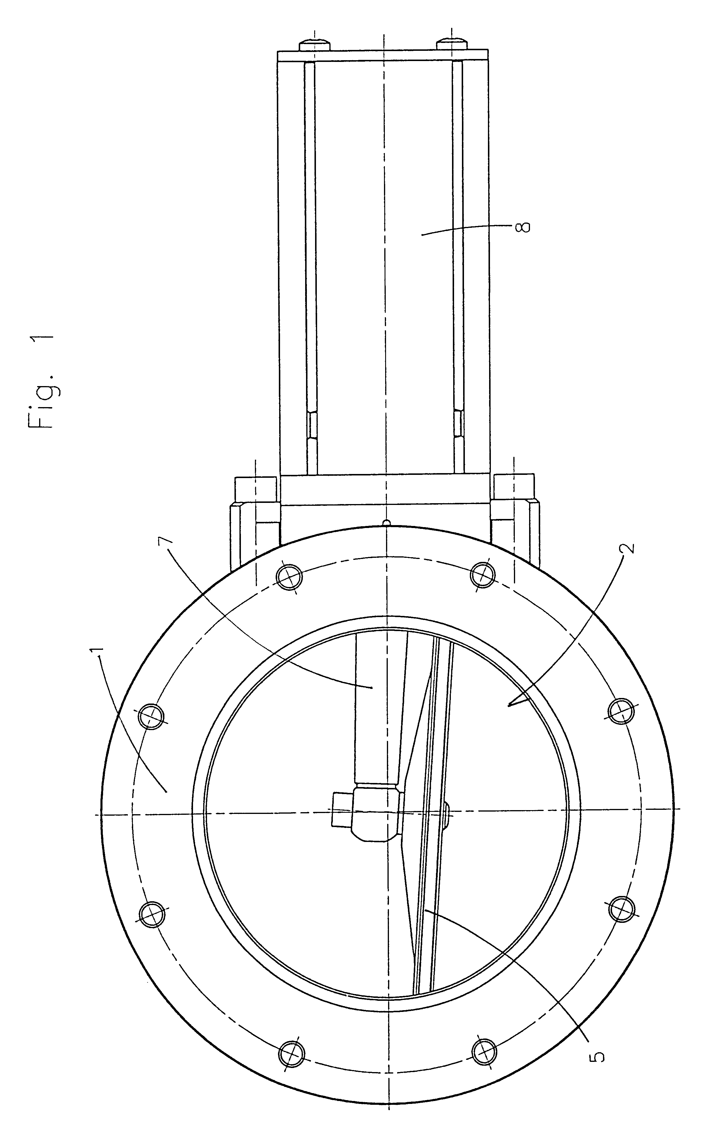
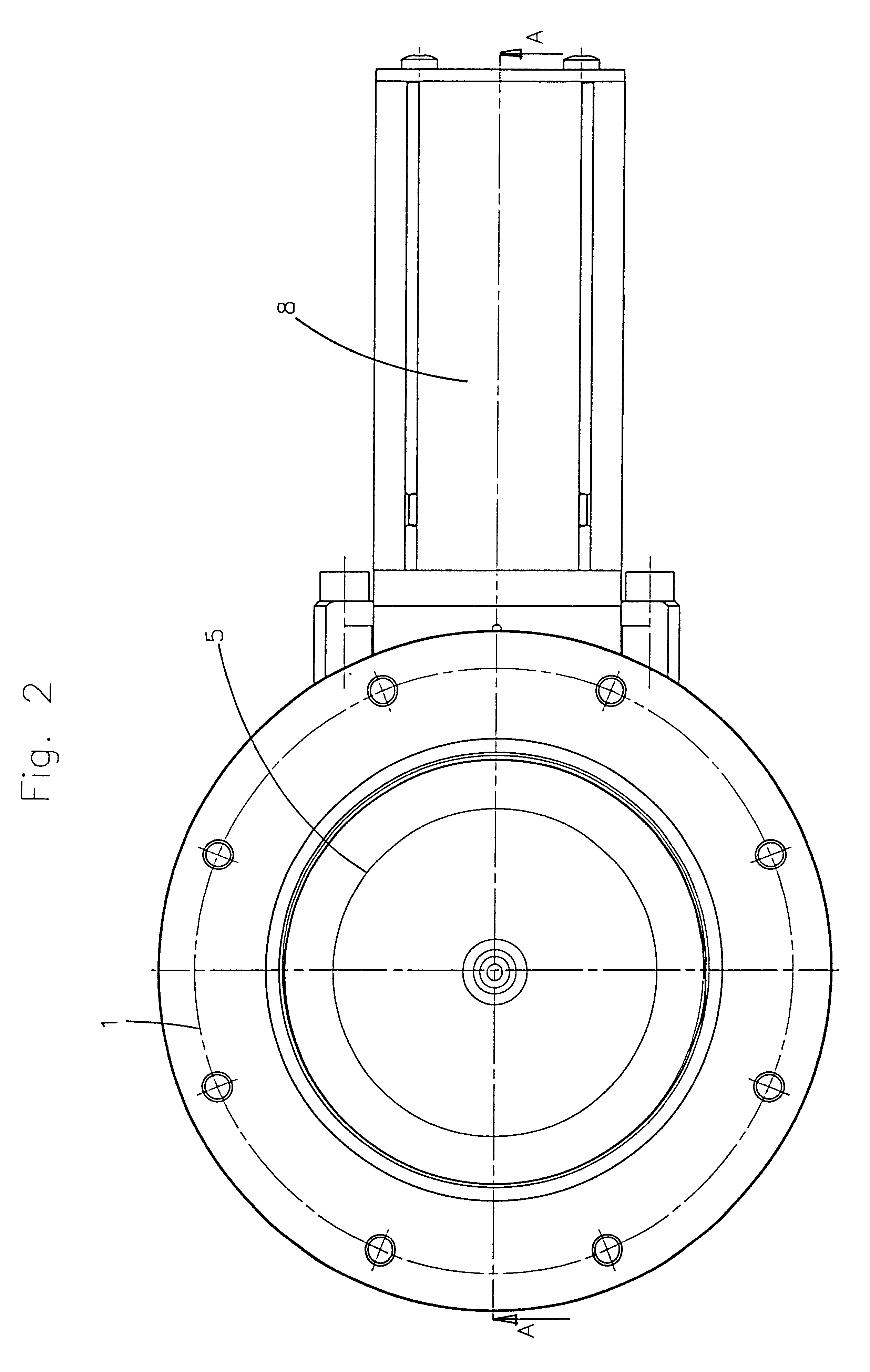
The butterfly valve shown in the drawings comprises a valve housing 1 with a valve opening 2 which narrows, e.g., conically or spherically toward one flange side 3 of the housing 1 (the center point of the narrowing spherical surfaces being located on the axis of rotation of the valve rod described in the following). These tapering or narrowing surfaces form a valve seat 4 for a valve plate 5. The valve plate 5 has a slotted edge with a circumferentially closed sealing ring 6 which is made of Viton, for example.

The valve plate 5 in the form of a relatively thin-walled circular disk is rigidly fastened to a valve rod 7 which acts centrally on the back of the valve plate 5. The valve rod is guided through the valve housing 1 by means of a vacuum through-guide which is described more exactly in the following and its end which protrudes from the valve housing projects into a cylinder 8, this cylinder being rigidly connected to the valve housing by screw connections.

The valve rod 7 is mo...


PUM


Abstract

A butterfly valve comprises a valve housing with a valve opening and a valve seat, this valve housing enclosing a vacuum area of the valve; a valve plate which is mounted at a valve rod guided through the valve housing and which is pressed against the valve seat in a closed position of the valve, tilted relative to the valve seat in a partially open position of the valve through tilting of the valve rod about a tilting axis, and tilted and rotated relative to the valve in a completely open position of the valve by subsequent rotation of the valve rod about its longitudinal axis; wherein the valve rod has portions extending on both sides of the tilting axis, the portion located on one side of the tilting axis acting centrally at the valve plate and the portion located on the other side of the tilting axis being connected, via a link guide which is located outside the vacuum area and which has a link with a part extending at an inclination to the longitudinal axis of the valve rod and a helical surface-shaped part and a journal which is guided in the link, to an actuating member which is mounted so as to be displaceable in axial direction of the valve rod.

Description

a) Field of the InventionThe invention is directed to a butterfly valve. In particular, the invention relates to a butterfly valve comprising a valve housing with a valve opening and a valve seat and a valve plate which is pressed against the valve seat in a closed position of the valve, is tilted relative to the valve seat in a partially open position of the valve and is tilted and rotated relative to the valve seat in a completely open position of the valve.b) Description of the Related ArtVacuum valves in the form of butterfly valves, as they are called, are known in different embodiment forms. In these butterfly valves, the valve plate is initially swiveled relative to the valve seat in order to open the valve and is then rotated by about , 90.degree. so that when the valve opening is viewed from the end only the narrow side of the valve plate is visible: and the valve plate accordingly essentially releases the valve opening. In order to impede the through-flow through the valve...

Claims


Application Information

Patent Timeline
Patent Type & Authority Patents(United States)
IPC IPC(8): F16K1/00F16K51/02F16K1/24F16K31/44
CPCF16K1/24F16K51/02Y10T74/18056Y10T74/18312
Inventor GEISER, FRIEDRICH
Owner VAT HLDG AG
Why Eureka
Try Eureka