
Feed pump

a technology of feed pump and casing, which is applied in the direction of liquid fuel engines, machines/engines, mechanical equipment, etc., can solve the problems of reducing the efficiency of feed pump, rubbing of the pump casing, and large play, and generating rattling noises

Inactive Publication Date: 2003-01-07
VITESCO TECH GERMANY GMBH
View PDF8 Cites 4 Cited by
  • Summary
  • Abstract
  • Description
  • Claims
  • Application Information

AI Technical Summary

Benefits of technology

This design effectively minimizes noise and enhances efficiency by preventing impeller rubbing and maintaining a consistent sealing gap, while ensuring correct impeller positioning for high performance.

Problems solved by technology

A problem with the known feed pump is that positional tolerances and the angle of inclination of the shaft with respect to the casing may lead to the impeller rubbing on the casing.
This rubbing generates loud noises and, moreover, reduces the efficiency of the feed pump.
However, the large play produces rattling noises when the shaft is driven and in the case of fluctuations in flow in the feed pump.

Method used


Image

  • Feed pump
  • Feed pump
  • Feed pump

Examples


Embodiment Construction

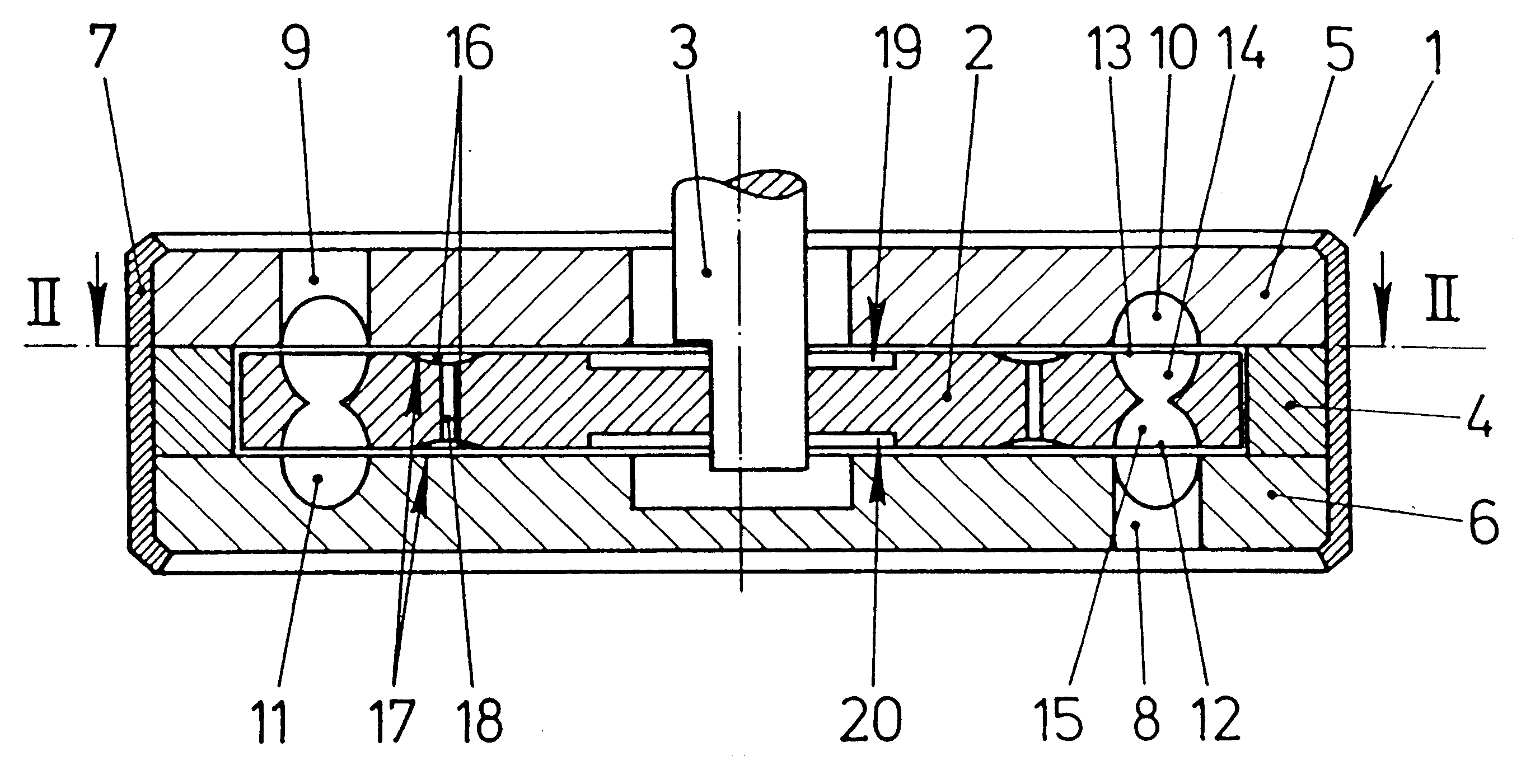
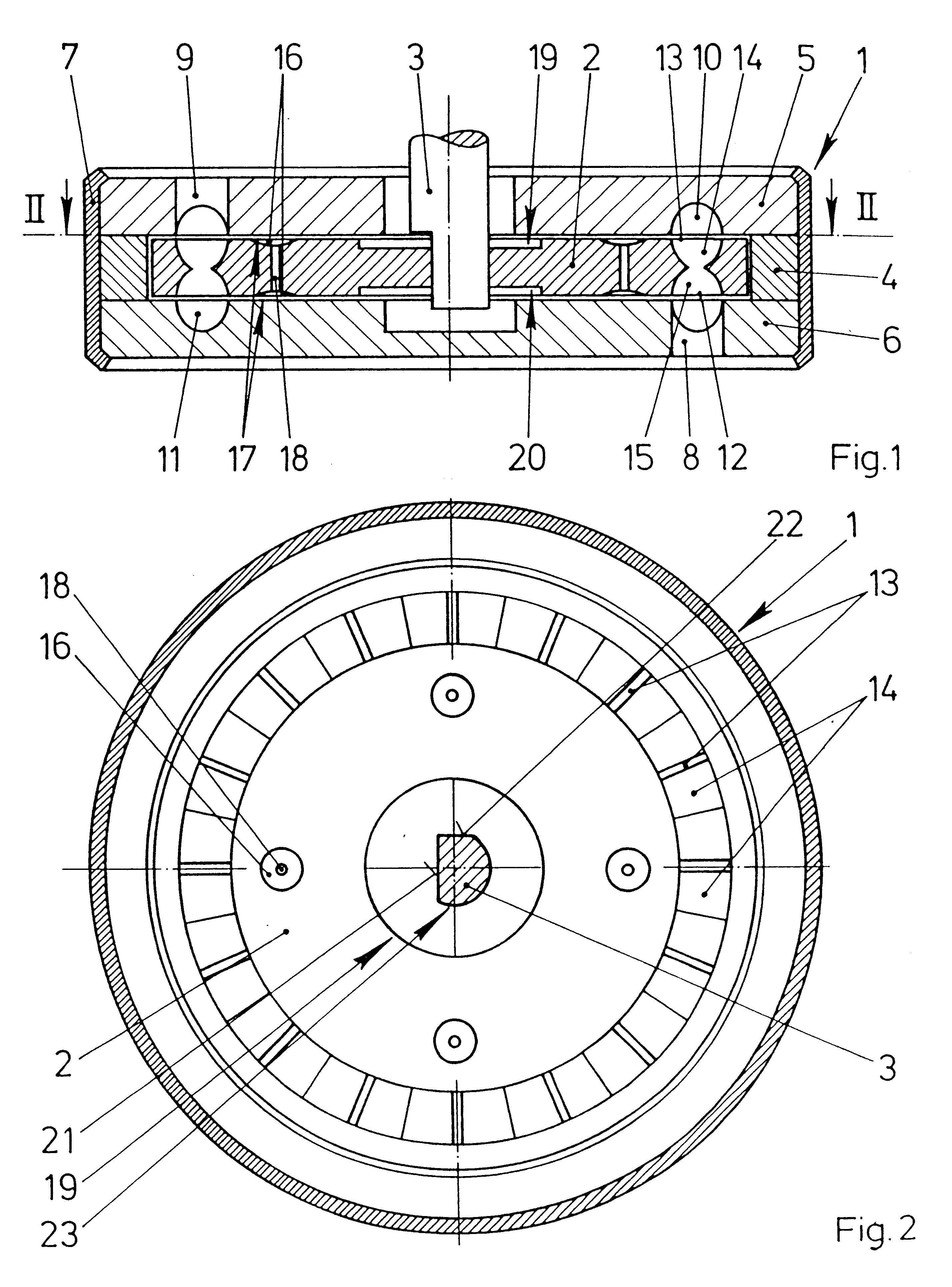
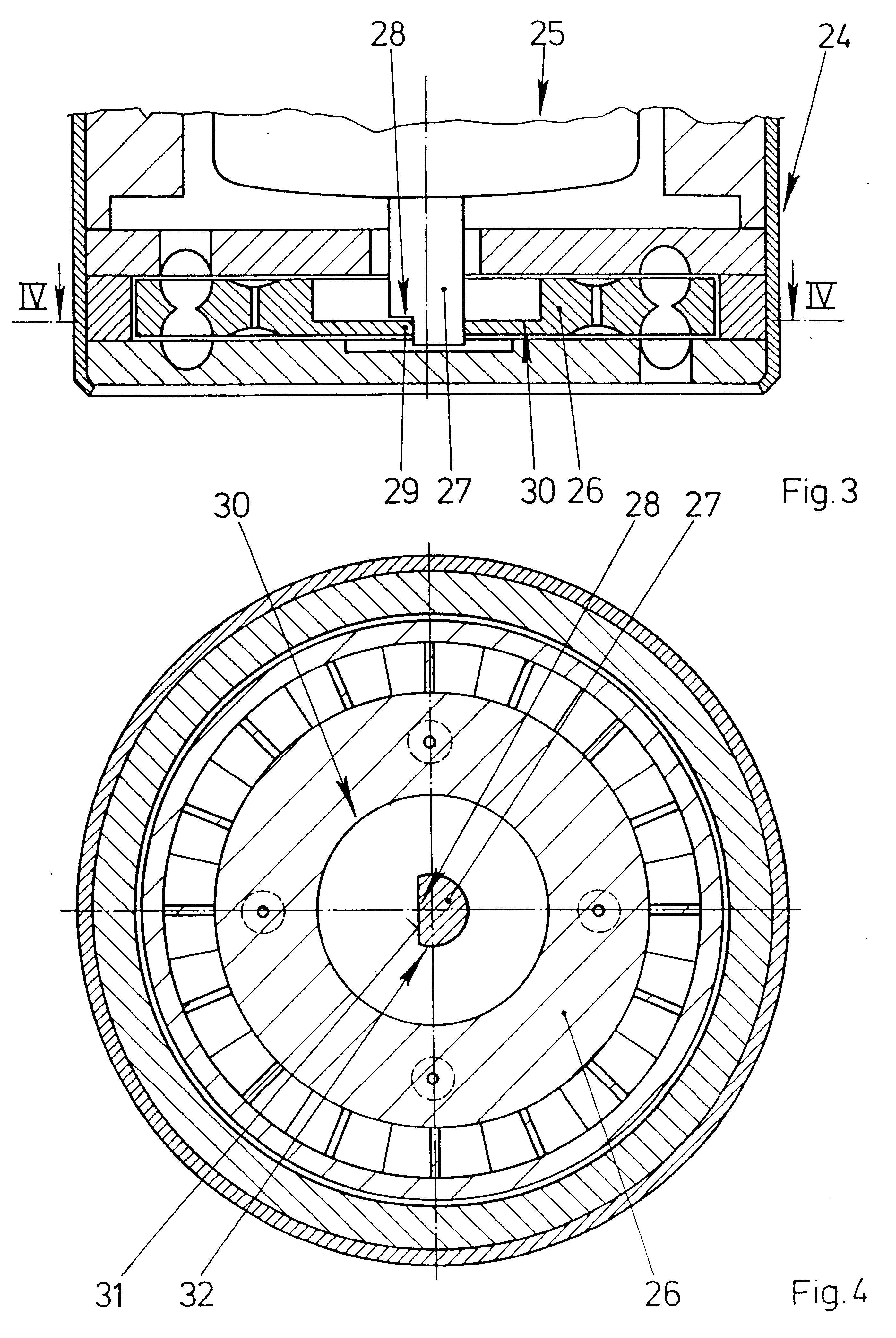
FIG. 1 is a sectional view of a feed pump according to the present invention designed as a side-channel pump with an impeller 2 rotatably arranged in a casing 1. The impeller 2 is arranged so that it is fixed with respect to rotation relative to a driven shaft 3 and slightly axially displaceable on the driven shaft 3. The shaft 3 may, for example, be designed as a motor shaft of an electric motor (the electric motor is not illustrated in FIG. 1). The casing 1 includes two casing parts 5, 6 held with clearance by a ring 4 and a sheet-metal strip 7 rolled at the edges of the casing parts 5, 6 and intended for prestressing the casing parts 5, 6 against the ring 4. An inlet channel 8 is arranged in one of the casing parts 6 and an outlet channel 9 is arranged in the other casing part 5. The inlet channel 8 and the outlet channel 9 are respectively connected to part-annular channels 10, 11. The impeller 2 has blade chambers 14, 15 arranged in the region of the part-annular channels 10, 1...


PUM


Abstract

In a feed pump designed as a side-channel pump, an impeller is held so as to be slightly pivotable with respect to a shaft about an axis running transversely to the shaft. The impeller is thereby adaptable to tolerances of a casing. Rubbing of the impeller on the casing is also prevented as a result. The feed pump consequently generates a particularly low level of noise.

Description

1. Field of the InventionThe invention relates to a feed pump for feeding fuel out of a fuel tank of a motor vehicle or for feeding washing fluid of a windshield washing system including a casing, an impeller arranged in the casing and connected on a driven shaft such that the impeller is fixed with respect to rotation relative to the driven shaft and a portion of the impeller is arranged with a slight clearance relative to the casing.2. Description of the Related ArtFeed pumps for feeding fuel out of a fuel tank or for feeding washing fluid for a windshield washing system are typically designed as peripheral pumps or side-channel pumps and are known from practice. Each of these known pumps includes a casing which usually has two casing parts with a recess for the impeller. A particularly small sealing gap is arranged between the impeller and the casing parts in radially outer regions of the impeller which are adjacent to guide blades. An axial sliding bearing is usually also arrang...

Claims


Application Information

Patent Timeline
Patent Type & Authority Patents(United States)
IPC IPC(8): F04D29/18F04D5/00
CPCF04D29/188F04D29/18
Inventor MARX, PETERJAGER, BERND
Owner VITESCO TECH GERMANY GMBH
Learn More