Method of and apparatus for curing an optical disc

a technology of optical discs and curing resins, applied in the field of methods and apparatus for curing optical discs, can solve the problems of lack of uniformity, ineffective and uniform curing of ultraviolet curing resins r, and complex structure of disc substrates constituting optical discs d

Inactive Publication Date: 2003-01-07
KITANO SEISAKU
View PDF13 Cites 19 Cited by
  • Summary
  • Abstract
  • Description
  • Claims
  • Application Information

AI Technical Summary

Problems solved by technology

However, as an optical disc D, such as a DVD, having a large storage capacity for information has recently become popular, the structure of disc substrates constituting the optical disc D is multilayered and becomes complex.
Further, if the structure of the disc substrate becomes complex, there occurs a case where ultraviolet does not at all pass through the disc substrate.
Even if disc substrates through which ultraviolet hardly transmits are used,

Method used


Image

  • Method of and apparatus for curing an optical disc
  • Method of and apparatus for curing an optical disc
  • Method of and apparatus for curing an optical disc

Examples


first embodiment

A method of and an apparatus for curing an optical disc according to a first embodiment of the invention are now described with reference to FIGS. 1 to 6.

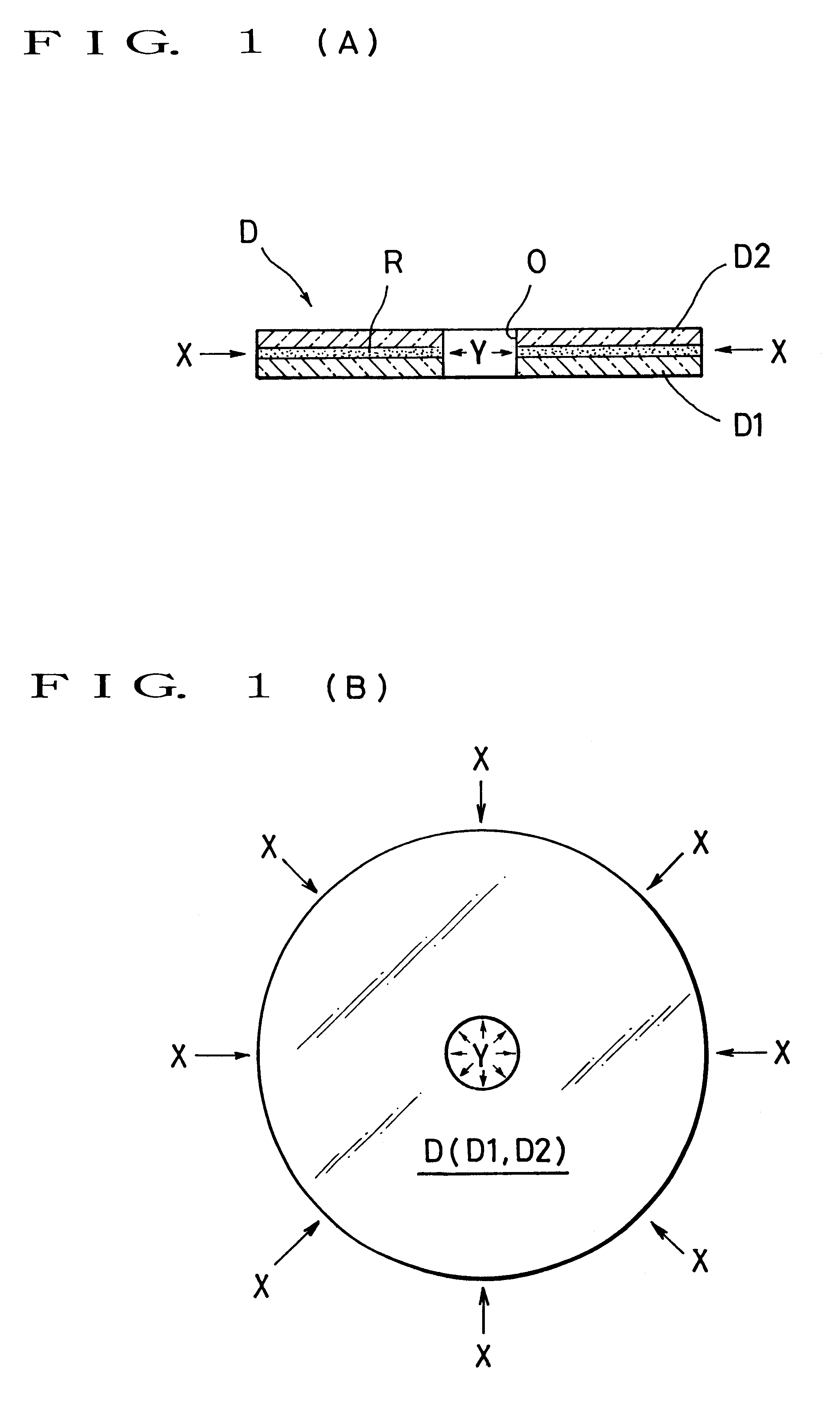
Ultraviolet emitted from an ultraviolet light source, not shown, is irradiated from a peripheral surface of the optical disc D toward the inner portion by the medium of optical transmission cables or parts 7 such as an optical fiber, then it is irradiated from the center (central hole) of the optical disc D toward the outer portion so as to cure the ultraviolet curing resin R (see FIG. 1).

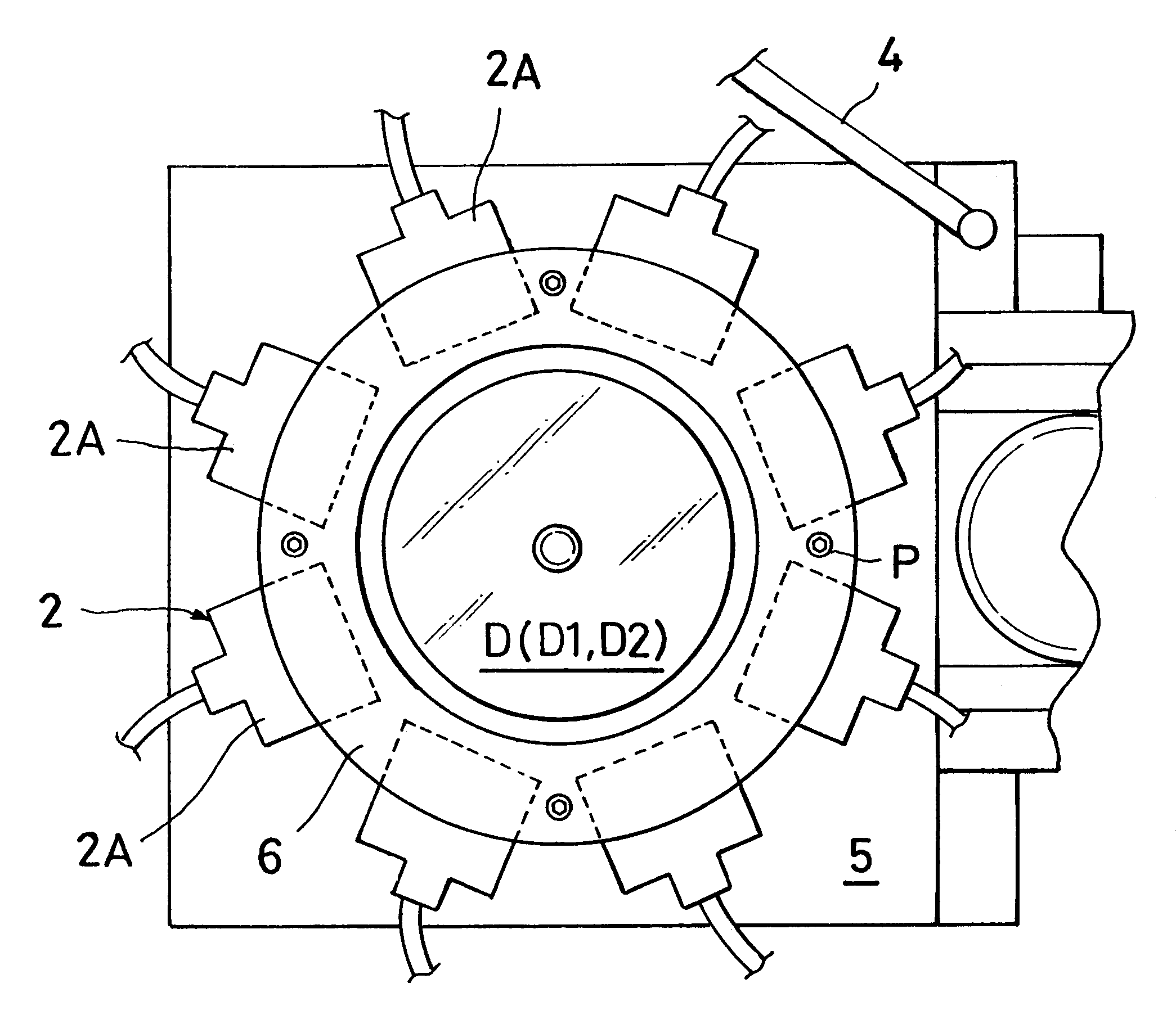
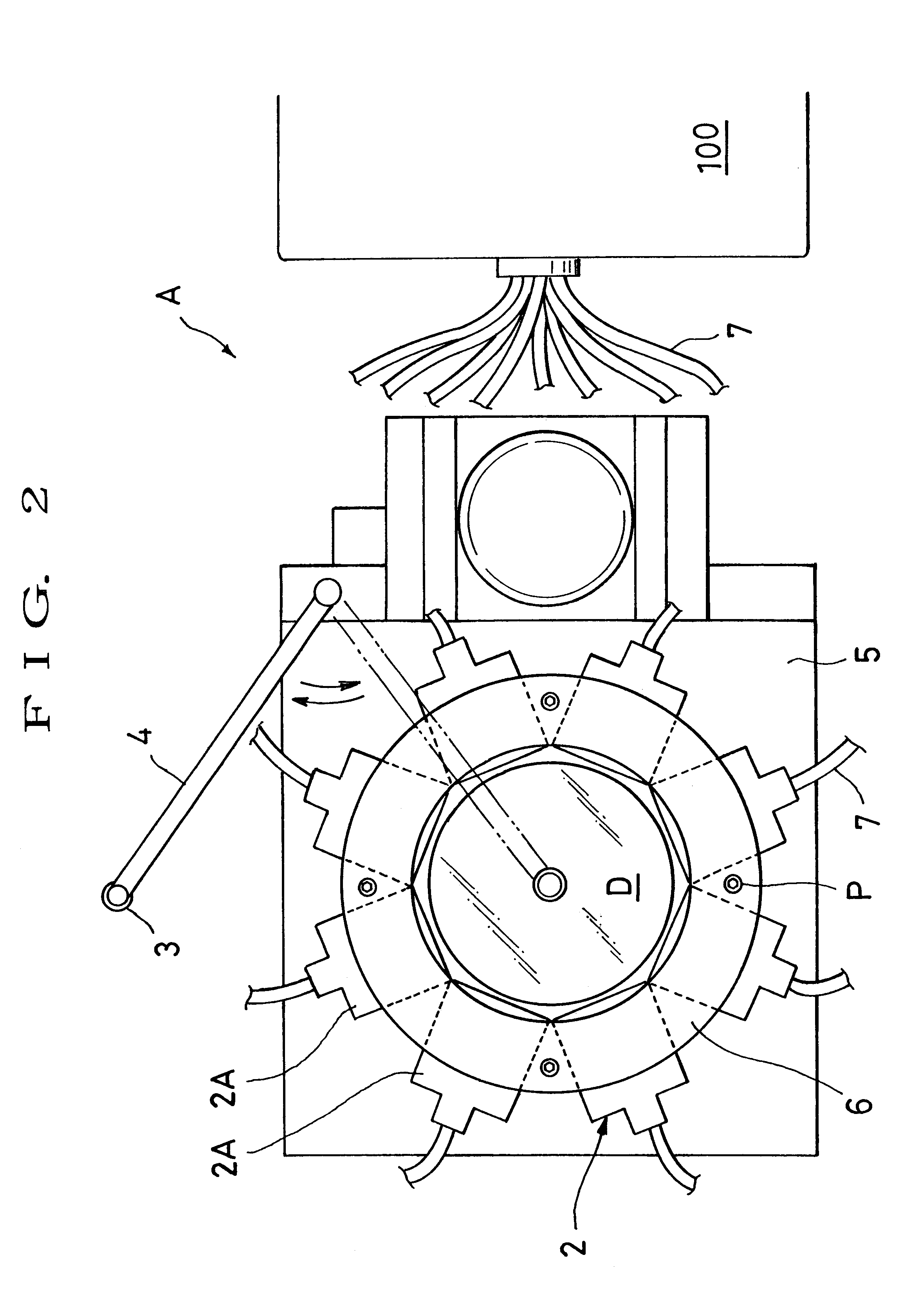
The apparatus for curing an optical disc D is described next with reference to FIGS. 2 to 5. FIGS. 2 and 3 are plan and side views respectively schematically showing the apparatus for curing an optical disc D wherein the optical disc D is irradiated with ultraviolet.

Meanwhile, FIGS. 4 and 5 are sectional views of the apparatus for curing an optical disc D, wherein FIG. 4 shows a state at the time before ultraviolet is irradiated and FIG. 5 shows a...

second embodiment

A ultraviolet irradiation peripheral unit 2 is divided in plural units or bodies and disposed along the peripheral surface of the optical disc D so as to irradiate ultraviolet from the peripheral surface of the optical disc D toward the inner portion thereof.

As the divided units or bodies 2A of the ultraviolet irradiation peripheral unit 2, it is particularly advantageous that pairs of divided bodies 2A, which are obtained by dividing the ultraviolet irradiation peripheral unit 2 into eight pieces, are arranged in parallel with each other and disposed so as to define square as shown in FIG. 7.

The reason is that if the divided bodies 2A of the ultraviolet irradiation peripheral unit 2 are disposed particularly in the direction of the central portion of the optical disc D, for example, if a fine foreign matter such as dust is mixed in the ultraviolet curing resin R serving as an adhesive, an area inside of the location of the foreign matter in the central direction becomes a shade S o...


PUM

PropertyMeasurementUnit
Angleaaaaaaaaaa
Forceaaaaaaaaaa
Pressureaaaaaaaaaa

Abstract

A method of and apparatus for curing an optical disc capable of efficiently curing ultraviolet curing resin serving as an adhesive between a pair of disc substrates. The apparatus includes a peripherally located ultraviolet irradiation unit disposed around a rotary holding table for irradiating ultraviolet from the peripheral surface of the optical disc toward the inner portion thereof so as to cure the ultraviolet curing resin, and/or a central irradiation unit disposed to irradiate ultraviolet from the central hole of the optical disc toward the outer portion thereof.

Description

1. Field of the InventionThe invention relates to a method of and an apparatus for curing an optical disc D, more particularly to a method of and an apparatus for curing an ultraviolet curing resin R efficiently and uniformly, which resin is sandwiched between two disc substrates constituting the optical disc D.2. Description of the Related ArtGenerally, an optical disc D has an information signal therein such as an image, sound, or the like which is transferred onto one side of a disc substrate made of polycarbonate in the form of signal pits (signal holes).In a relatively simple structure of an optical disc D, a metallic reflection film made of, e.g. aluminum, is provided on the surface of the signal pits, and a protection film such as an ultraviolet curing resin R film is formed on the metallic reflection film for preventing damage to the metallic reflection film.However, as an optical disc D, such as a DVD, having a large storage capacity for information has recently become popu...

Claims


Application Information

Patent Timeline
IPC IPC(8): B29C65/00B29C65/48B29C35/08
CPCB29C65/1406B29C65/1448B29C65/1451B29C65/1467B29C65/4845B29C65/521B29C65/7847B29C66/452B29C65/1483B29C66/3452B29C66/65B29C2035/0827B29L2017/005Y10S425/81B29C66/8322B29C66/71B29C66/72321B29C66/1122B29K2069/00
Inventor KITANO, RYOKOINOUCHI, MASAMIYOSHIDA, MASAYUKI
Owner KITANO SEISAKU
Why Eureka
Try Eureka