Multi-layered LC composite with a connecting pattern capacitively coupling inductors to ground

a technology of capacitively coupling inductors and composite components, applied in waveguides, waveguide devices, electrical devices, etc., can solve the problems of increased insertion loss, inability to achieve the effect of increasing attenuation

Inactive Publication Date: 2003-01-07
MURATA MFG CO LTD
View PDF3 Cites 81 Cited by
  • Summary
  • Abstract
  • Description
  • Claims
  • Application Information

AI Technical Summary

Benefits of technology

To overcome the above-described problems, preferred embodiments of the present invention provide a multi-layered LC composite component that greatly increases the amount of attenuation in the proximity of a central frequency without increasing an insertion loss.

Problems solved by technology

However, to increase the amount of attenuation in the proximity of the central frequency, when another attenuation pole is added on the high-frequency side of the central frequency, for example, in the proximity of a central frequency F.sub.0 +0.12 GHz, it is not possible to achieve the increased attenuation.
In addition, when a plurality of attenuation poles is added in the proximity of the central frequency, increased insertion loss occurs.

Method used


Image

  • Multi-layered LC composite with a connecting pattern capacitively coupling inductors to ground
  • Multi-layered LC composite with a connecting pattern capacitively coupling inductors to ground
  • Multi-layered LC composite with a connecting pattern capacitively coupling inductors to ground

Examples


Embodiment Construction

Referring to the attached drawings, a description will be provided of preferred embodiments of a multi-layered LC composite component according to the present invention.

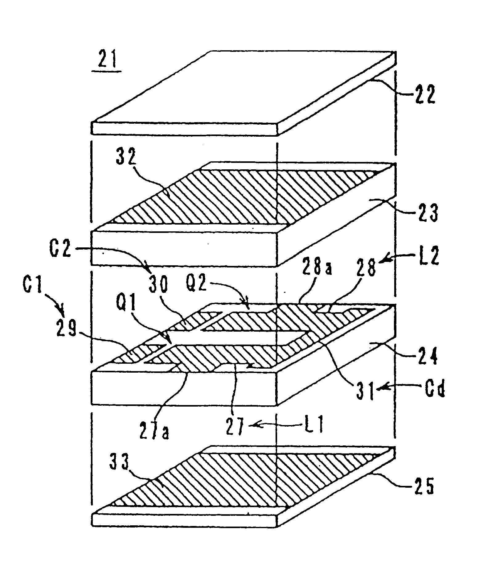
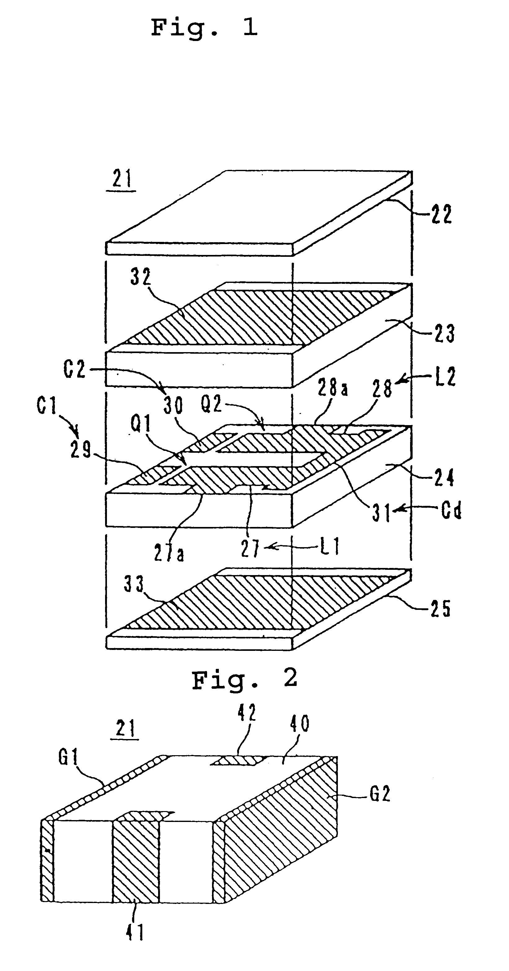
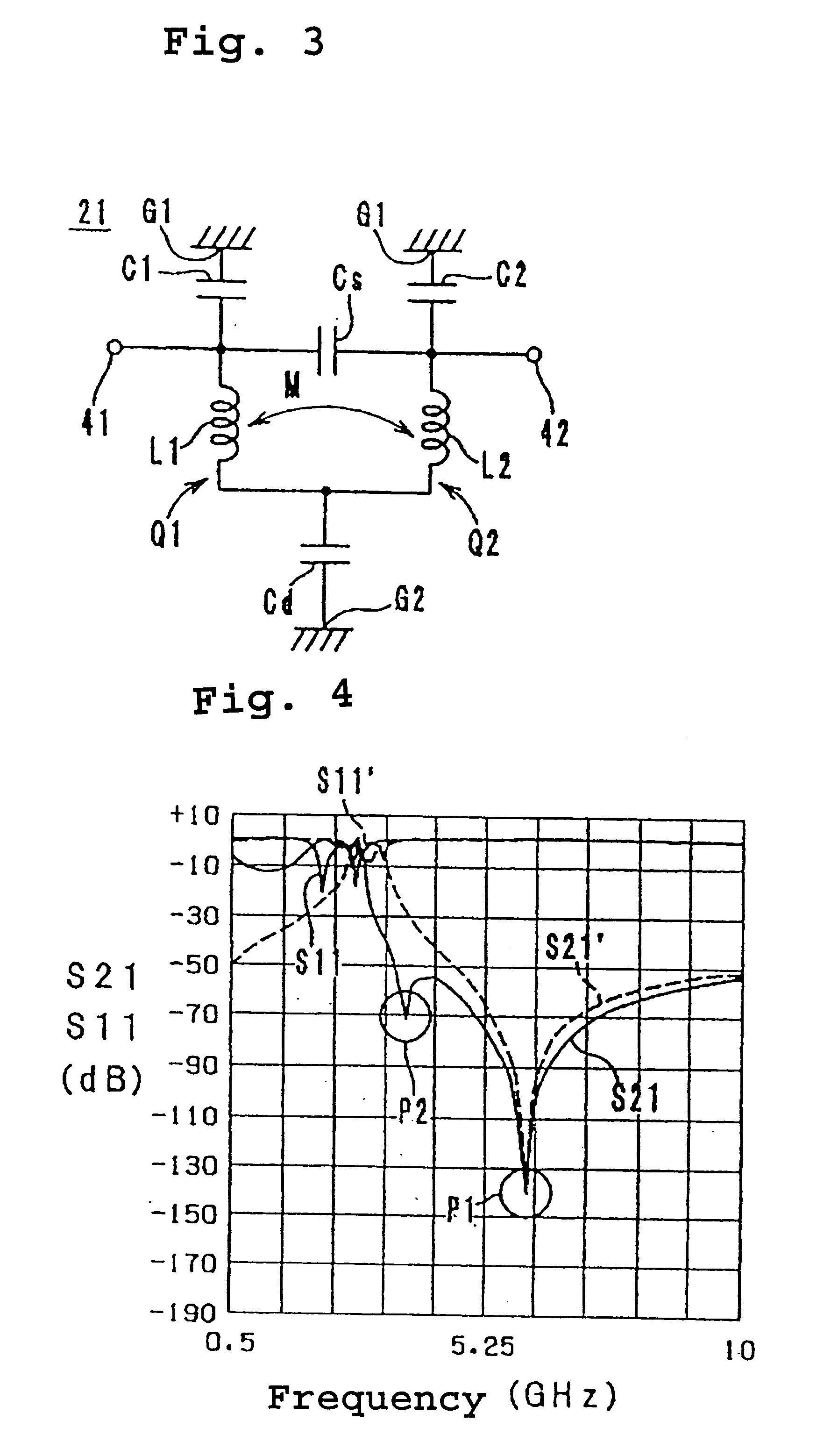
FIG. 1 shows the structure of a multi-layered LC composite filter 21 according to a first preferred embodiment of the present invention. FIG. 2 shows a perspective view of the LC filter 21, and FIG. 3 shows an electrically equivalent circuit diagram thereof. The LC filter 21 is a two-stage filter having LC resonators Q1 and Q2.

As shown in FIG. 1, the multi-layered LC filter 21 includes an insulating sheet 24 having inductor patterns 27 and 28, frequency-adjusting capacitor patterns 29 and 30, and a connecting pattern 31 provided thereon, an insulating sheet 23 having a shield pattern 32 provided thereon, an insulating sheet 25 having a shield pattern 33 provided thereon, and an insulating sheet 22. The insulating sheets 22 to 25 are formed by mixing a dielectric powder and a magnetic powder with a binding agent. The ...


PUM


Abstract

A multi-layered LC composite component achieves greatly increased attenuation in the proximity of a central frequency without increasing insertion loss. In the arrangement of the multi-layered LC composite component, an end of each of inductor patterns is connected to a connecting pattern to be short-circuited. These inductor patterns define inductors. Frequency-adjusting capacitor patterns are opposed to open-circuited ends of the inductor patterns to define capacitors. As a result, the capacitors and the inductors define LC resonators. The connecting pattern is opposed to shield patterns via insulating sheets to define a common capacitor.

Description

1. Field of the InventionThe present invention relates to multi-layered LC composite components, and more particularly relates to multi-layered LC composite components included in high-frequency bands.2. Description of the Related ArtA conventional multi-layered LC filter is shown in each of FIGS. 15 and 16. As shown in FIG. 15, a multi-layered LC filter 1 includes a ceramic sheet 4 having inductor patterns 7 and 8 and frequency-adjusting capacitor patterns 9 and 10 provided thereon, and ceramic sheets 3 and 5 having shield patterns 12 and 13 provided thereon, and a ceramic sheet 2.The ceramic sheets 2 to 5 are laminated and subsequently integrally fired to define a multi-layered structure 15 shown in FIG. 16. On the multi-layered structure 15, an input terminal 16, an output terminal 17, and ground terminals G1 and G2 are provided. The input terminal 16 is connected to a leading portion 7a of the inductor pattern 7. The output terminal 17 is connected to a leading portion 8a of the...

Claims


Application Information

Patent Timeline
Patent Type & Authority Patents(United States)
IPC IPC(8): H03H7/01H03H7/09
CPCH03H7/0115H03H7/1708H03H7/1725H03H7/1791H03H7/09H03H7/1758H03H2001/0085
Inventor YAMAGUCHI, NAOTO
Owner MURATA MFG CO LTD
Why Eureka
Try Eureka