Allograft bone fixation screw

a technology of screw and socket, which is applied in the field of threaded devices, can solve the problems of premature failure of the screw during intraoperative insertion, compromise the functionality of the fixation, and material failure to meet the expected performance,

Inactive Publication Date: 2003-01-14
MUSCULOSKELETAL TRANSPLANT FOUND INC
View PDF17 Cites 137 Cited by
  • Summary
  • Abstract
  • Description
  • Claims
  • Application Information

AI Technical Summary

Benefits of technology

Thus the present screw design is both easy to use and offers the ideal physiological response of patient tissue to allograft bone tissue.

Problems solved by technology

The most significant difficulties with screws and pins currently used to facilitate fixation include the residual presence of "hardware" that may migrate, include adverse tissue reaction to the presence of foreign particulate debris, and otherwise compromise the functionality of the fixation.
Unfortunately, these materials may fall short of expected performance due to incomplete osseointegration of patient bone.
However, the conventional slotted or rectangular head designs commonly used in metal screws when used with allograft bone screws, result in premature failure of the screws during intraoperative insertion due to excessively high shear forces applied to the head and the transition between the head and threaded portion of the screw.
First, and foremost, while bone is quite strong in compressive loading, it is relatively weak in tension and shear.
There are several problems with screws presently used in the prior art.
As can be appreciated, the screws are small with a round or cylindrical head and are difficult to place in the driver or area to be fastened because of the nature of the surgery, namely that the same are used in circumstances where fluid such as blood is present, thus, presenting a slippery condition for handling and use.
In addition, the use of a cylindrical barrel or round head on the screw is not the most efficient way of transmitting torque to the screw when the same is screwed into the bone and the present invention allows a maximum torque to be applied over the driver head portion of the screw allowing the same to be more easily inserted.

Method used


Image

  • Allograft bone fixation screw
  • Allograft bone fixation screw
  • Allograft bone fixation screw

Examples


Embodiment Construction

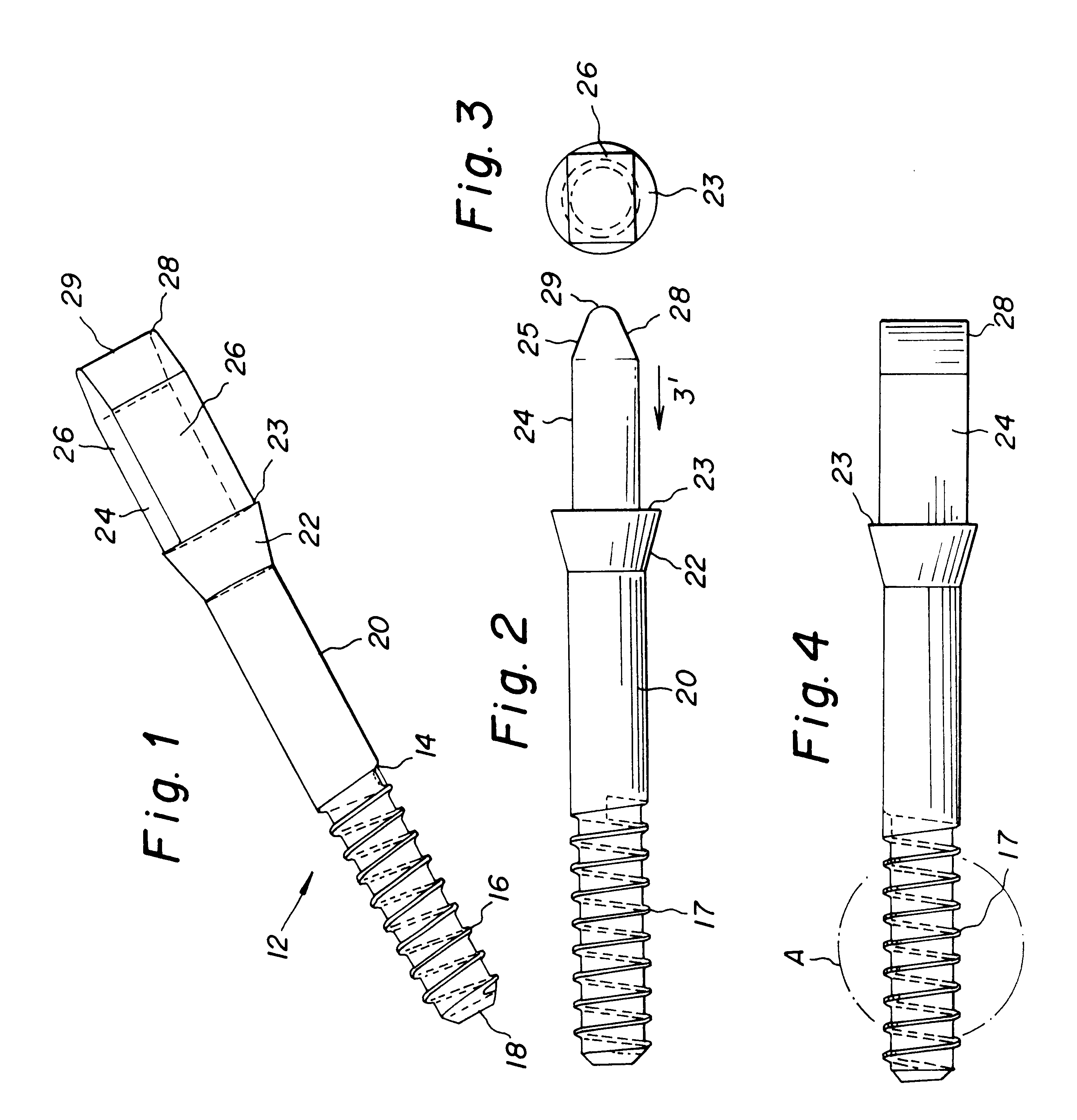
The preferred embodiment and the best mode of the present invention is shown in FIGS. 1 through 5.

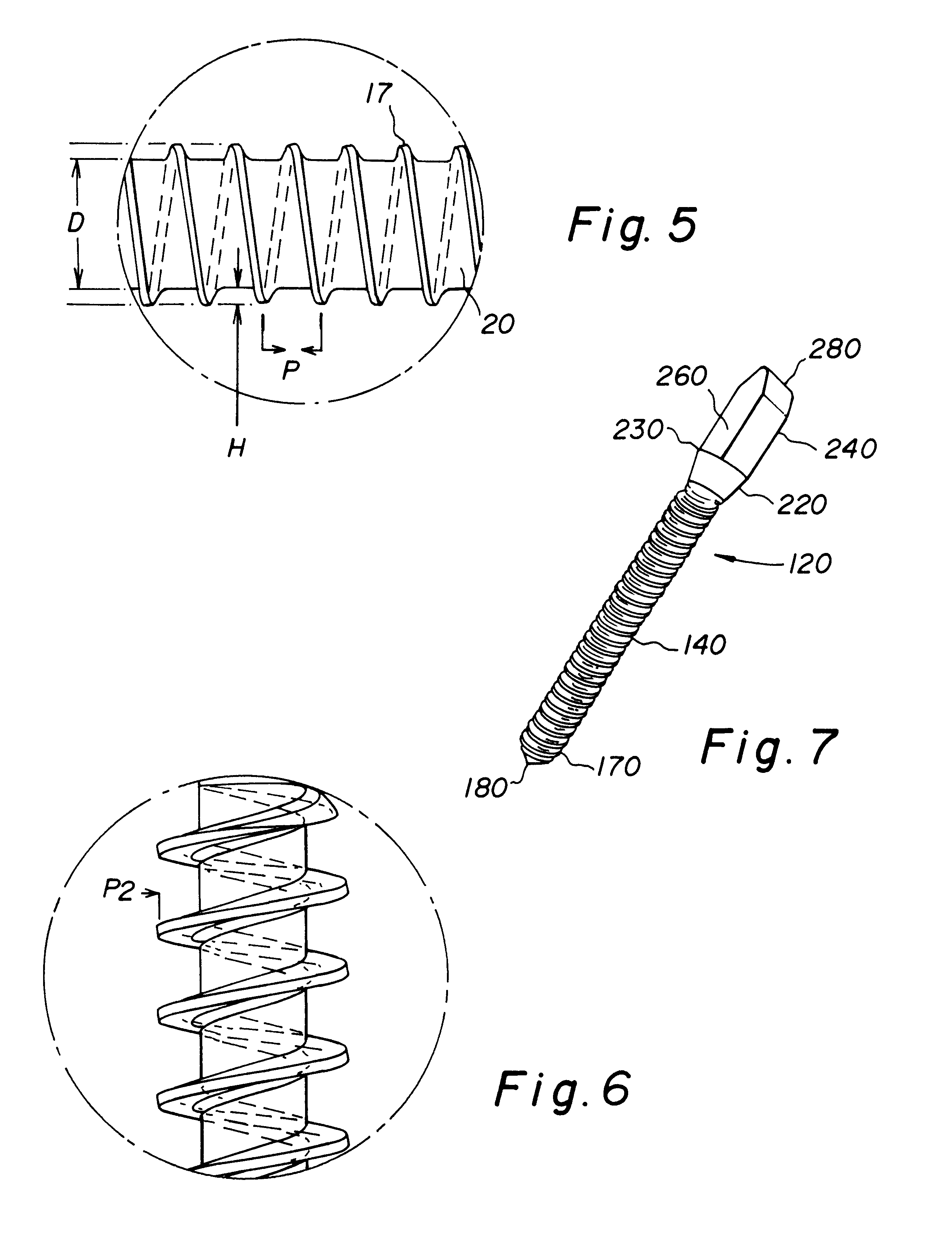
It is an accepted fact that the initiation of mechanical failure in a material occurs at the outer surface of the material. Also, it is recognized that rapid changes in cross sectional geometry act as localized "stress risers", significantly increasing the risk of failure under load. The present inventive bone screw 12 solves these problems particularly when the screw is constructed of allograft bone. The preferred material of the bone screw is cortical allograft bone.

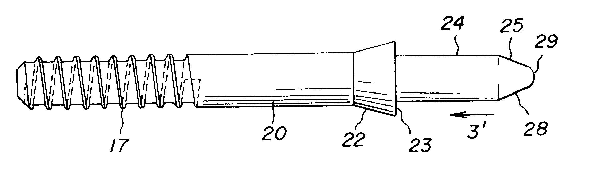
The bone fixation screw 12 has a shark 14 with a threaded portion 16 ending in a distal tip 18 and an unthreaded portion 20 which has a section 22 is tapered outward to form a frustrum conical configuration with a flat end portion 23 from which a drive head 24 extends. The flat end portion preferably has a 4.0 mm or -0.1 mm diameter with the sides of the drive head ranging from 3.0 mm to 4.0 mm in width. The drive head 24 ...


PUM


Abstract

A sterile allograft bone screw comprising a screw shank with a uniform diameter threaded portion, an unthreaded portion with a outwardly tapered conical portion and a rectangularly shaped driving head portion with substantially wedge shaped end which can be engagably seated in a seat of a driver member.

Description

1. Field of InventionThe present invention generally relates to threaded devices used to facilitate bone fracture or osteotomy fixation in human surgery and more specifically relates to threaded devices made of allograft bone.2. Description of the Prior ArtThe prior art contains many references directed to fastener drivers which drive screws having a Phillips head, standard slot head or other heads having various shaped slots or recesses which receive the torque from the driver end. See for example the prior art shown in U.S. Pat. No. 5,367,926. There are other examples of prior art fastener drivers having female driver ends which receive and drive fasteners having a male torque receiving end. Typical driver screw fasteners and screws of such a construction are shown in U.S. Pat. Nos. 755,804; 1,300,275; 4,724,731; 5,012,624; 5,443,482 and 5,730,744. Wrenches having a female driving end which drive caps or nuts are shown by U.S. Pat. Nos. 1,336,794 and 4,823,650.Several patents such...

Claims


Application Information

Patent Timeline
Patent Type & Authority Patents(United States)
IPC IPC(8): A61B17/86A61B17/68A61B17/88A61B19/00A61F2/00
CPCA61B17/8605A61B17/861A61B17/8625A61B17/8877Y10S606/909A61B2019/307A61F2/0077A61B17/866A61B2090/037
Inventor GERTZMAN, ARTHUR A.FERRARA, JR., RAYMOND G.HAINES, TIMOTHY G.
Owner MUSCULOSKELETAL TRANSPLANT FOUND INC
Why Eureka
Try Eureka