
Reduced impedance chamber

a technology of impedance chamber and reduction chamber, which is applied in the field of reduced impedance chamber, can solve the problems of process uniformity problems or non-normal ion-accelerating electric field, processing is difficult to control, and coupling impedances can vary significantly

Inactive Publication Date: 2003-01-28
TOKYO ELECTRON LTD
View PDF21 Cites 43 Cited by
  • Summary
  • Abstract
  • Description
  • Claims
  • Application Information

AI Technical Summary

Problems solved by technology

In many systems, there are areas of the chamber wall that function as the counter electrode; if these walls are too close to the wafer, then they generate process uniformity problems or non-normal ion-accelerating electric fields.
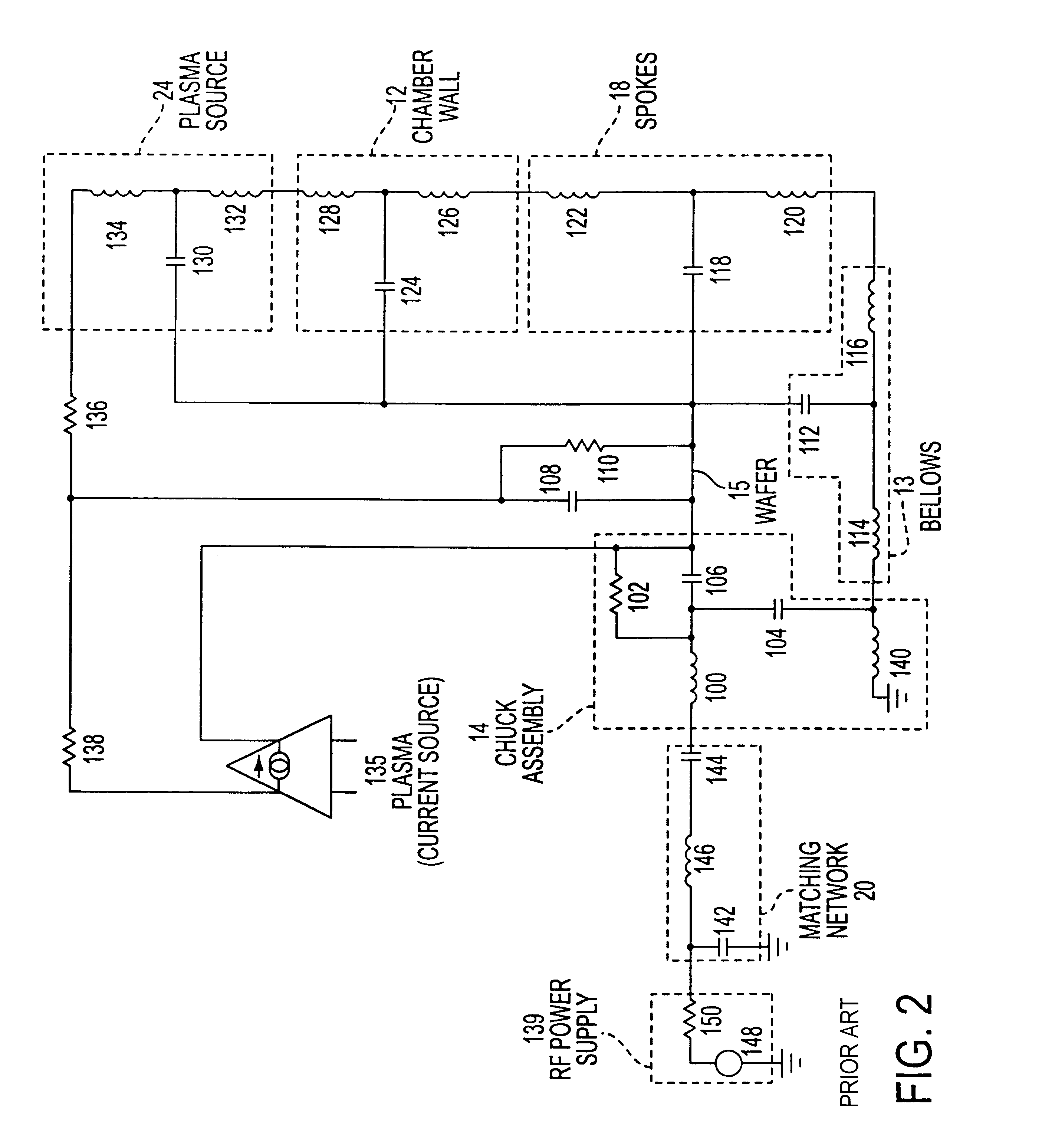
The generally nonlinear impedances of the elements described above result in the generation of higher order harmonics in the plasma voltage at the workpiece whereby the processing is difficult to control.
Likewise, coupling impedances can vary significantly because of manufacturing or refitting errors.
Thus, the processing is not easily repeatable because of factors that may change from one processing sequence to another and from one chamber to another and thereby affect the level of the higher order harmonics.

Method used


Image

  • Reduced impedance chamber
  • Reduced impedance chamber
  • Reduced impedance chamber

Examples


Embodiment Construction

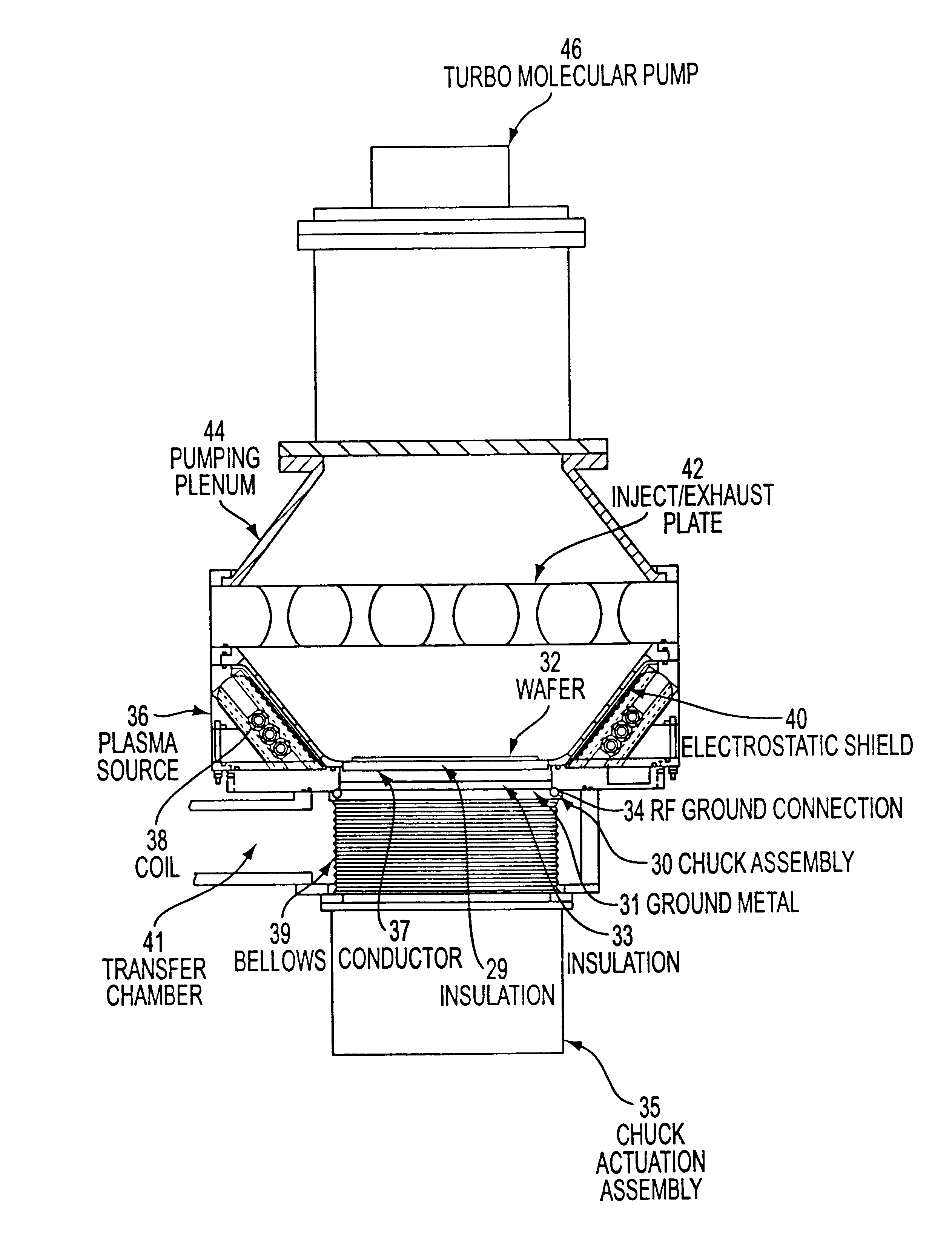
The diagram of a preferred embodiment of the reduced impedance chamber of the present invention in FIG. 5 includes a chuck assembly 30 upon which is mounted a workpiece such as a semiconductor wafer 32. RF energy may be applied to wafer 32 through capacitive coupling to RF driven chuck assembly 30. Plasma source 36 includes a coil 38 and an electrostatic shield 40. An inject-exhaust plate 42 is connected to plasma source 36. Inject-exhaust plate 42 is also connected to a pumping plenum 44 and a turbo-molecular pump 46.

Chuck assembly 30 comprises a conductor 37 to which RF energy is applied, layers of insulation 29 and 33 and a ground metal 31. Insulation layer 29 separates conductor 37 from wafer 32 while insulation layer 33 separates conductor 37 from ground metal 31. Conductor 37 may include one or more conducting portions to create either a single-pole or a multi-pole chuck. Chuck assembly 30 is connected to a chuck actuation assembly 35 through a bellows 39 and linkages (not sho...


PUM

PropertyMeasurementUnit
Temperatureaaaaaaaaaa
Volumeaaaaaaaaaa
Electrical conductanceaaaaaaaaaa

Abstract

A reduced impedance chamber for plasma processing leads to operational advantages including a plasma sheath voltage that is substantially independent of plasma impedance over a range of plasma impedances. The design of such a reduced impedance chamber includes a chuck assembly, a counter electrode, and a plasma source. The chuck assembly allows mounting of a workpiece for processing and includes a driven electrode and a ground portion. The plasma source operates to generate a plasma in the chamber from process gas. A wall portion of the plasma source is directly electrically connected to the counter electrode and to the ground portion of the chuck assembly. The counter electrode may include an inject-exhaust plate that is mounted in a position opposed to the chuck assembly and that operates to inject process gas into the chamber and to exhaust effluent.

Description

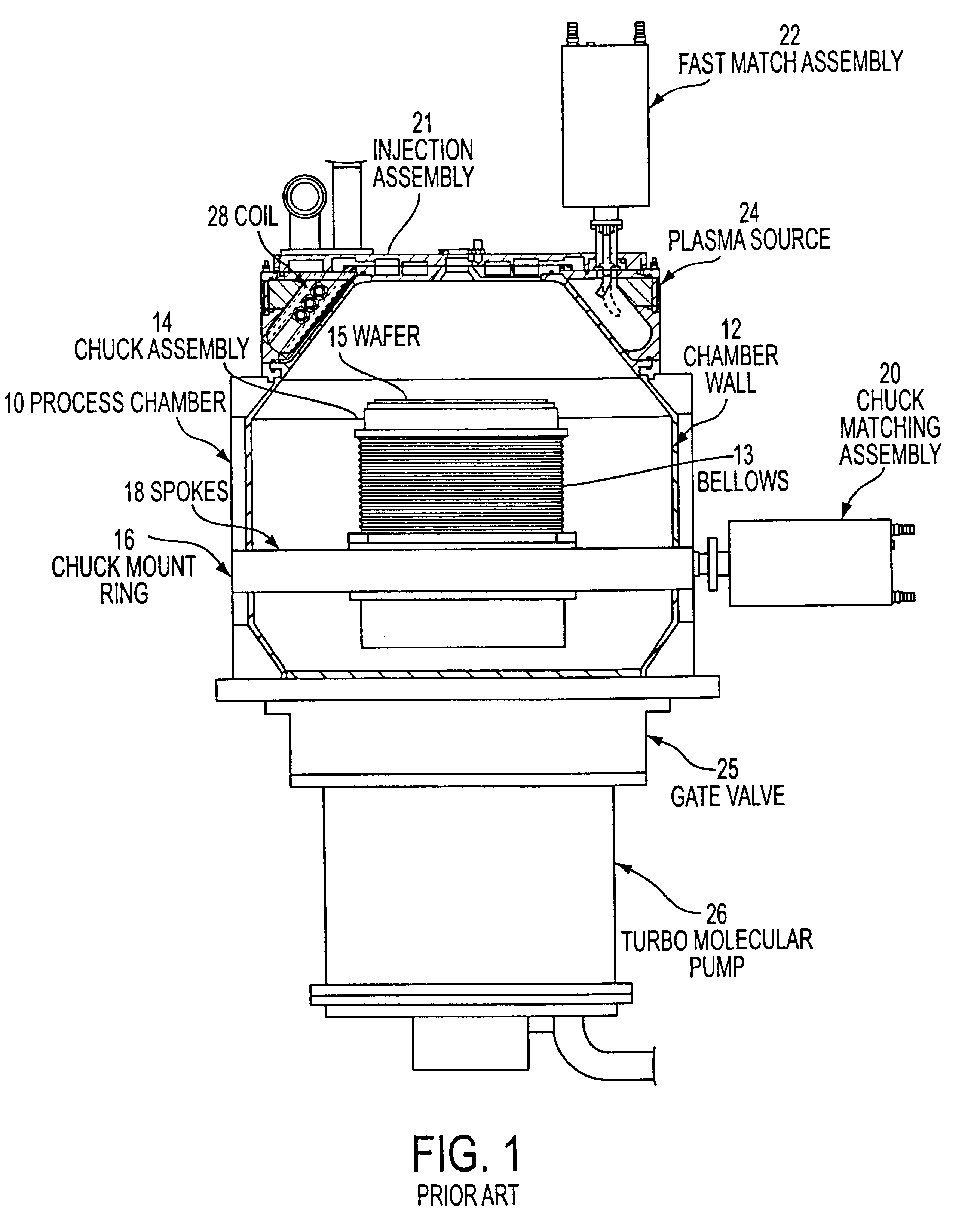
1. Field of InventionThe present invention relates to a reduced-impedance chamber for use in plasma processing applications and more particularly to a chamber that can be used in repeatable and controllable plasma processing applications.2. Description of Related ArtA conventional chamber, as shown in FIG. 1, includes a process chamber 10 having a chamber wall 12. A chuck assembly 14 is mounted on a bellows 13 that is mounted on a chuck mount ring 16. Chuck mount ring 16 includes spokes 18 through which chuck mount ring 16 is connected to chuck assembly 14. A workpiece, such as a semiconductor wafer 15, is mounted on chuck assembly 14. RF energy can be applied to chuck assembly 14 through a chuck impedance matching assembly 20. A plasma source 24 and an injection assembly 21 through which operational gases are injected into chamber 10 are above chuck assembly 14. A turbo-molecular pump 26 for evacuating operational gases is below chuck assembly 14. A gate valve 25 between chuck asse...

Claims


Application Information

Patent Timeline
IPC IPC(8): H01J37/32H01L21/00B01J3/00H05H1/46B01J3/02C23C16/44H01L21/205H01L21/302H01L21/3065
CPCC23C16/4412H01J37/32082H01J37/32174H01L21/67069H01J37/32724H01J37/32834H01J37/3244C23F1/02
Inventor JOHNSON, WAYNE L.
Owner TOKYO ELECTRON LTD
Learn More