Adhesive tape

a technology of adhesive tape and adhesive ring, which is applied in the field of adhesive tape, can solve the problems of tearing and tensile load, disadvantages of a very high price, and inability to prevent tearing at the edges damaged subsequently

Inactive Publication Date: 2003-01-28
TESA SE
View PDF11 Cites 50 Cited by
  • Summary
  • Abstract
  • Description
  • Claims
  • Application Information

AI Technical Summary

Problems solved by technology

This leads to tearing and tensile load in the case, for example, of rough edges of film and, respectively, adhesive tape (caused by blunt blades during cutting or subsequent unintended damage to the cut edge).
The use of woven fabrics offers a comprise at a higher level, albeit with the disadvantages of a very much higher price and further operations such as coating in order to seal the surface.
However, it does not prevent tearing at edges damaged subsequently; this necessitates a drastic improvement in the tear propagation resistance, possessed only by the coextruded film of the invention with an internal structure.
The raw materials specified for the abovementioned invention, for increasing the toughness, however, lead to markedly reduced longitudinal strength, especially the raw materials of the tough coextrusion layer.
In terms of equipment, the production of such filament adhesive tapes is very complex and thus expensive, and susceptible to faults.
In addition to the base film, there is an additional requirement for the filaments and laminating adhesive (or additional pressure-sensitive adhesive coating), which makes the products more expensive and ties up a greater quantity of raw material resources.
Further disadvantages of such filament adhesive tapes are the low crease fracture stability, the unclean cut edges, and the absence of weldability and recyclability.
The films are unoriented and offer no reinforcing effect.
The method is not applicable to polypropylene, since the customary gel fraction automatically blocks the filament channels of the die.
The films are unoriented and therefore of only low longitudinal strength.
The essential defect of this invention, however, is that it cannot be produced on a...

Method used


Image

  • Adhesive tape
  • Adhesive tape
  • Adhesive tape

Examples


example 1

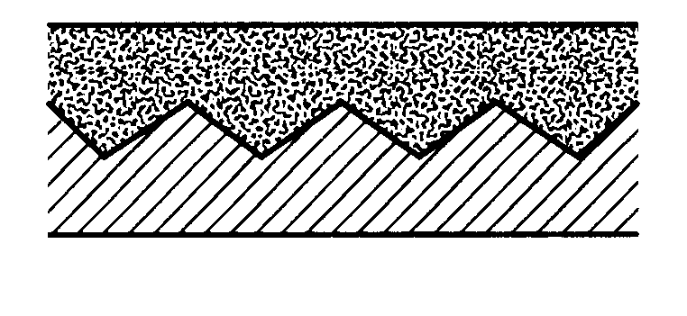
The film is produced on an extrusion unit in a width of 60 cm using a die as shown in FIG. 2 (three-layer intemal-combining manifold die with exchangeable central plate for generating melt streams with a predetermined profile), a chill roll and a single-stage short-gap drawing unit. The definition of the layers is as follows: Layer 3 lies on the chill roll, layer 1 is the middle layer, layer 2 lies on the air side. The interface between layers 1 and 3 is smooth and that between layers 2 and 1 is intermeshed. The process conditions are as follows:

Raw materials mixture Extruder 1: 50% Shell Polystyrene N 7000 (homopolymer), 50% Stamylan P 83MF10 Block-Copolymer (trivial name: polypropylene)

Raw materials mixture Extruder 2: 5% Shell Polystyrene N 7000 (homopolymer), 95% Stamylan P 83MF10 Block-Copolymer

Raw materials mixture Extruder 3: 75% Stamylan P 83MF10 Block-Copolymer, 25% Stamylex 1026 (LLDPE).

Jaw heating 240.degree. C., chill roll 18.degree. C., film speed prior to drawing 1.5 m...

example 2

Equipment as Example 1. Process conditions:

Raw materials mixture Extruder 1: 50% Shell Polystyrene S 5400 (high impact), 50% Moplen EPQ 30 RF (copolymer-trivial name: polypropylene)

Raw materials mixture Extruder 2: 10% Shell Polystyrene S 5400 (high impact), 90% Moplen EPQ 30 RF

Raw materials mixture Extruder 3: 50% Shell Polystyrene S 5400 (high impact), 50% Moplen EPQ 30 RF.

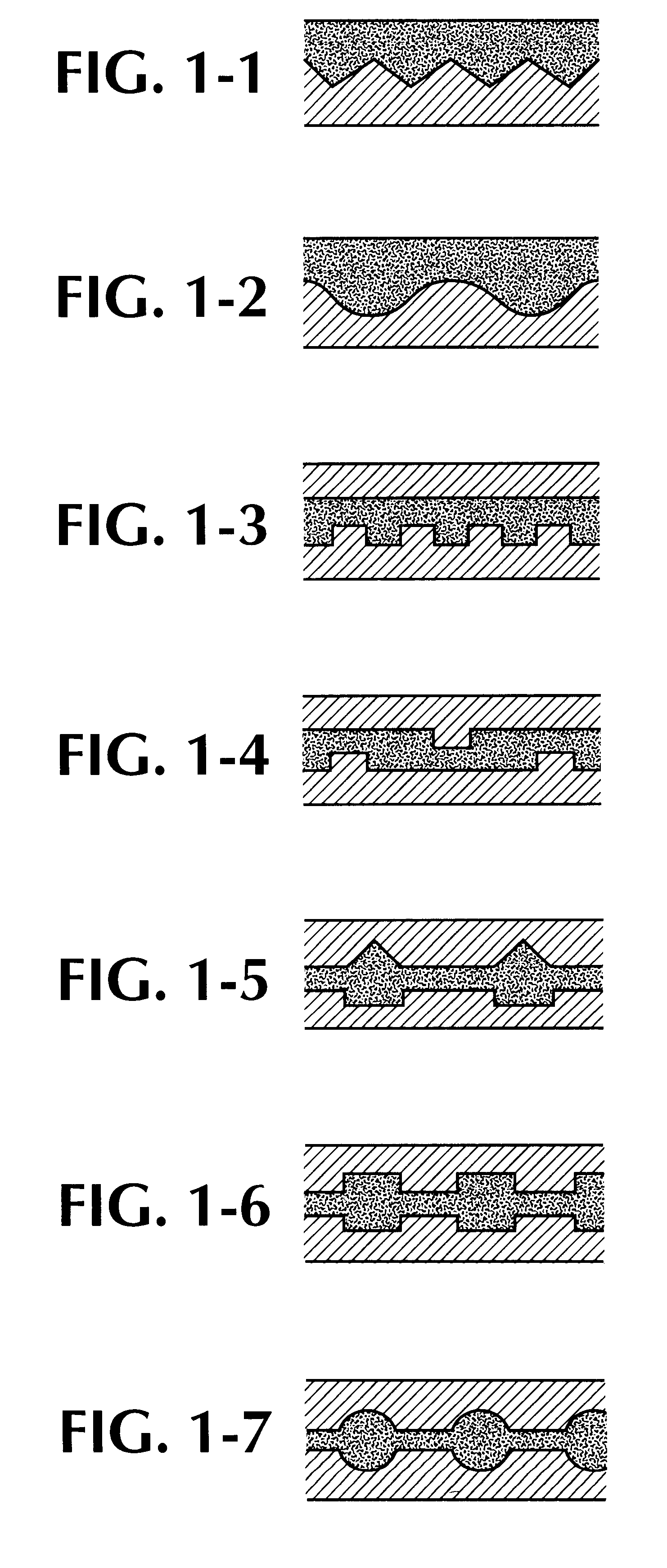
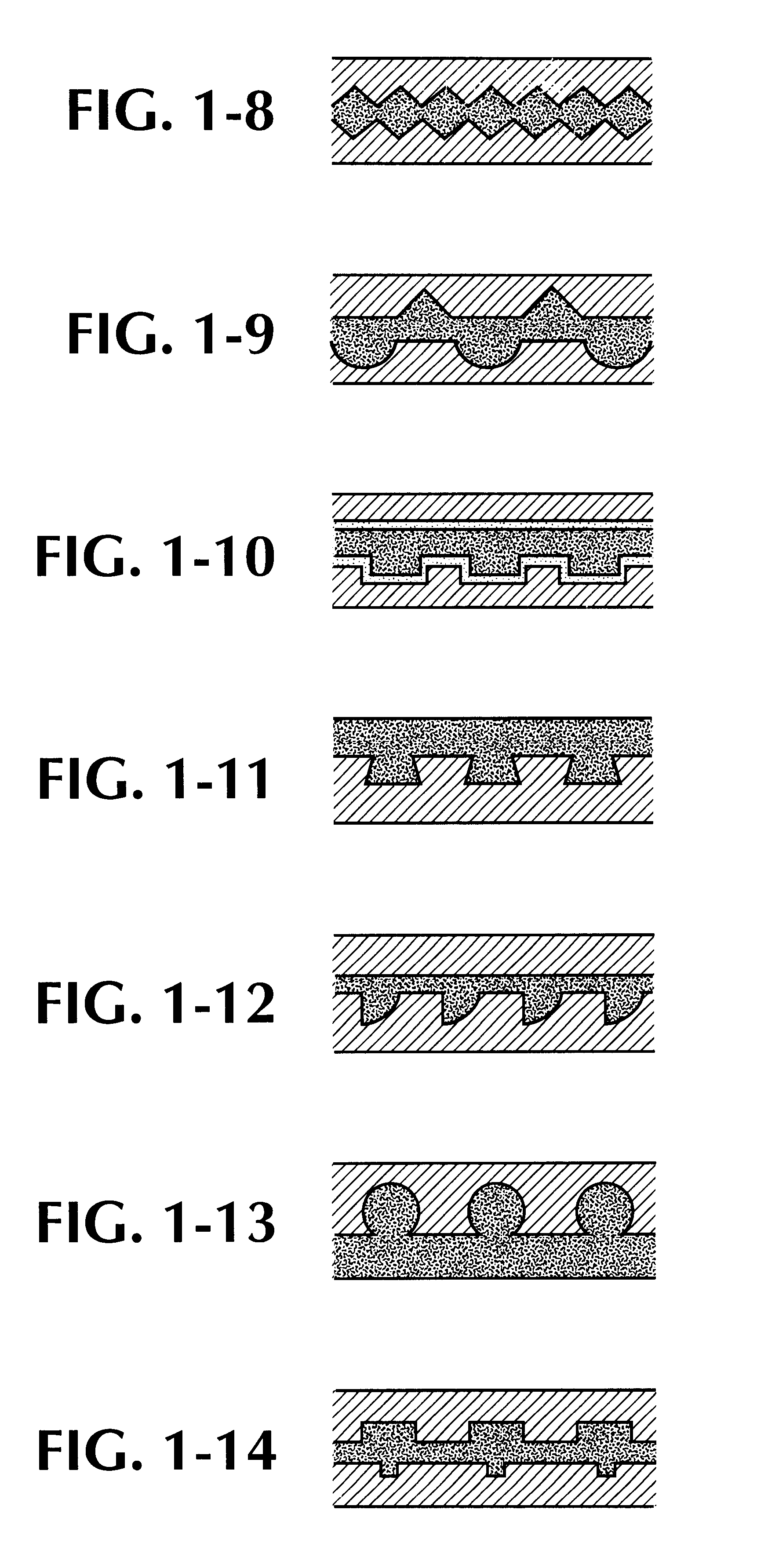
Jaw heating 240.degree. C., chill roll 18.degree. C., film speed prior to drawing 3.6 m / min, after drawing 24.7 m / min, draw ratio 1:6.7. The profile of the central plate produces a repeating rectangular profile between layers 2 and 1; the amplitude of the rectangles is 0.4 mm and the phase spacing is 2 mm.

The film is corona-pretreated on both sides, coated on the top face with a solvent-free silicone, which is subsequently crosslinked using electron beams. The underside is provided with a primer comprising natural rubber, cyclo rubber and 4,4'-diisocyanatophenylmethane. The adhesive is dissolved in hexane in a c...

example 3

Equipment as Example 1. Process conditions:

Raw materials mixture Extruder 1: 50% Shell Polystyrene S 5400, 50% Moplen EPQ 30 RF

Raw materials mixture Extruder 2: 100% Moplen EPO 30 RF

Raw materials mixture Extruder 3: 100% Moplen EPQ 30 RF

Jaw heating 240.degree. C., chill roll 18.degree. C., film speed prior to drawing 1.5 m / min, after drawing 13.1 m / min, draw ratio 1:8.7. The profile of the central plate produces a repeating profile of semicircles between layers 2 and 1; the radius of the semicirles is 0.2 mm and the phase spacing is 2.4 mm.

The film is corona-pretreated on the underside, coated with an aqueous acrylate pressure-sensitive adhesive (Primal.TM. PS 83 D) and dried at 115.degree. C. in a drying tunnel. The adhesive tape is subsequently wound up to form the stock roll and for further testing is cut (razor cutter) to a width of 15 mm. Bond strength to steel 3.2 N / cm, unwind force at 30 m / min 3.5 N / cm.


PUM

PropertyMeasurementUnit
Fractionaaaaaaaaaa
Forceaaaaaaaaaa
Forceaaaaaaaaaa

Abstract

An adhesive tape which comprises: (1) a backing film, wherein the backing film has at least two intermeshed coextruded layers of different composition, whose interface has a nonlinear course in cross section, which continues laminarly in the machine direction and has been oriented in the machine direction, and has plane-parallel outer faces; and (2) at least one adhesive layer which is attached to the backing film.

Description

The invention relates to a film oriented in the machine direction, having plane-parallel outer faces and at least two coextruded layers of different composition whose interface is not planar but instead has a nonlinear course in cross section, which continues laminarly in the machine direction, and to a process, by coextrusion and orientation, for its preparation, and to an adhesive tape produced therefrom.The particular internal structure of the film derives from the fact that the thickness of one layer varies periodically or irregularly in the cross-direction and the second layer compensates the fluctuations in thickness such that the overall thickness is essentially constant.The essential technical characteristic of the invention is the combination of lateral tear resistance (tear propagation force and residual strength) and longitudinal strength (tensile strength and stress at 10% elongation) in the machine direction.PRIOR ARTFilms possessing high longitudinal strength are norma...

Claims


Application Information

Patent Timeline
IPC IPC(8): B32B27/00C09J7/02B29C55/02B29C48/08B29C48/21B29C48/49B32B3/30B32B27/08C08J5/18C09J7/29C09J107/00C09J133/00C09J153/02C09J183/04C09J201/00
CPCB29C47/0021B29C47/065B29C47/067B29C47/145B32B27/00C09J7/0296B29C47/56Y10T428/2848C09J2201/162C09J2423/006C09J2425/006Y10S428/91Y10T428/28C09J7/29B29C48/08B29C48/21B29C48/22B29C48/307B29C48/49C09J2301/162B32B27/302B32B3/06B32B27/32B32B2325/00B32B27/08B32B2405/00B32B2323/10
Inventor MUSSIG, BERNHARDSCHMEER, GERT
Owner TESA SE
Why Eureka
Try Eureka