Solid-state radiation detector in which signal charges are reduced below saturation level

a solid-state radiation detector and signal charge technology, applied in the field of radiation detectors, can solve the problems of radiation producing quantization noise, high radiation through material transmission, and increasing the amount of fluorescent light emitted from the scintillator

Inactive Publication Date: 2003-02-04
FUJIFILM HLDG CORP +1
View PDF10 Cites 28 Cited by
  • Summary
  • Abstract
  • Description
  • Claims
  • Application Information

AI Technical Summary

Benefits of technology

In order to achieve the above object, according to the present invention, the amounts of charges generated by photoelectric conversion elements are reduced while maintaining great radiation absorption in the scintillator.
The left side of the above inequality corresponds to the amount of the charges generated by each photoelectric conversion element when the radiation detector is exposed to a radiation dose determined by the above number X. Therefore, the above relationship indicates that the amount of the charges generated by each photoelectric conversion element is not greater than the maximum storable charge amount Q of each capacitor element in the desirable range of the radiation dose, 10 to 300 mR. Thus, when the above relationship is satisfied, a sufficiently large dynamic range of the radiation dose can be realized even when the amount of radiation absorption in the scintillator is increased in order to reduce quantization noise.
(i) The radiation detector according to the first aspect of the present invention may further comprise a light-absorbing member arranged between the scintillator and the plurality of photoelectric conversion elements so as to decrease the entrance efficiency T.
(ii) The relationship can be satisfied by differently arranging the wavelength-light emission characteristic of the scintillator and the wavelength-sensitivity characteristic of each of the plurality of photoelectric conversion elements so as to decrease the photoelectric conversion efficiency .eta..
(iv) The plurality of pixels are two-dimensionally arranged, and the plurality of photoelectric conversion elements and the plurality of capacitor elements are arranged corresponding to the plurality of pixels, and integrally formed with the scintillator. When the plurality of photoelectric conversion elements and the plurality of capacitor elements are integrally formed with the scintillator, it is possible to reduce the amount of blur which is caused by gaps between the scintillator and the plurality of photoelectric conversion elements. In addition, the size of the radiation detector can be reduced. Alternatively, when the plurality of photoelectric conversion elements and the plurality of capacitor elements are formed separately from the scintillator, the characteristics of the respective constituents can be independently arranged so that the above relationship is satisfied, i.e., flexibility and replaceability is increased.

Problems solved by technology

In addition, the radiation absorption in the scintillator is required to be great in order to reduce quantization noise and achieve emission of a great amount of fluorescent light, although generally, transmittance of radiation through material is high, and radiation produces quantization noise.
However, when the thickness of the scintillator is increased, the amount of the fluorescent light emitted from the scintillator increases, and the amounts of charges generated in the photoelectric conversion elements also increase.
In other words, it is impossible to secure a sufficient dynamic range of the radiation dose.

Method used


Image

  • Solid-state radiation detector in which signal charges are reduced below saturation level
  • Solid-state radiation detector in which signal charges are reduced below saturation level
  • Solid-state radiation detector in which signal charges are reduced below saturation level

Examples


concrete examples

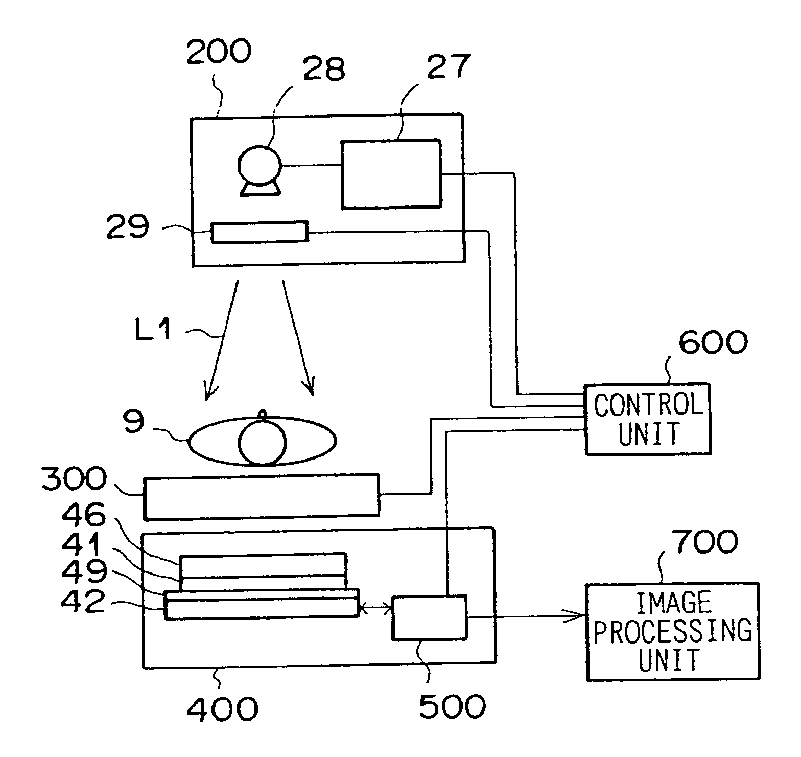
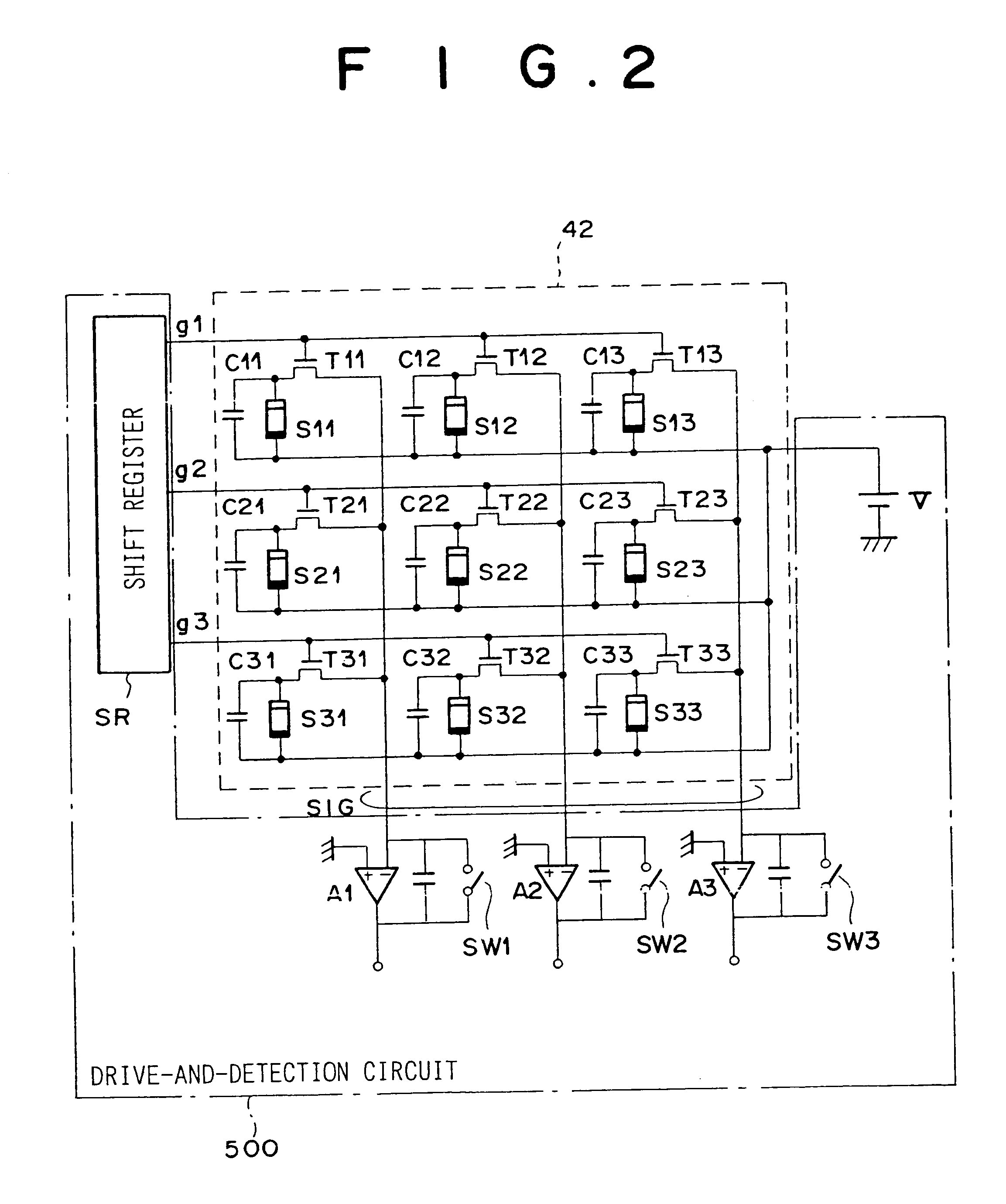
Concrete examples of the solid-state radiation detectors according to the present invention are indicated below for various amounts of the radiation dose. In the following examples, the solid-state radiation detectors include a typical CsI:Tl scintillator and a typical photoelectric conversion element containing Si as a main component, the capacitance C of the capacitor portion of each photoelectric conversion element is 2 pF, the voltage V applied to each photoelectric conversion element is 5 V, the maximum storable charge amount Q is 6.times.10.sup.7 e (where e is the elementary charge), the number L of photons which constitute fluorescent light emitted from the CsI:Tl scintillator in response to each radiation quantum is 2,000, the entrance efficiency T is 80%, the fill factor F of each photoelectric conversion element is 70%, and the photoelectric conversion efficiency .eta. of each photoelectric conversion element is 80%.

case 1

(1) Case 1

In the case 1, the radiation dose is 10 mR, and the number X of radiation quantums received in each pixel is 7 .times.10.sup.4.

(1-1) First Method (Use of Light Absorbing Member)

According to the first method, an optical filter as the aforementioned light absorption member 49 is arranged between the scintillator 41 and the solid-state radiation detector 42, where the optical filter realizes an entrance efficiency T of 50%. In this case, the amount Q0 of charges generated in each photoelectric conversion element becomes Q0=X.multidot.L.multidot.T.multidot.F.multidot..eta.=3.9.times.10.sup.7, which is not greater than the maximum storable charge amount Q=6.times.10.sup.7. That is, the aforementioned relationship Q0=X.multidot.L.multidot.T.multidot.F.multidot..eta..ltoreq.Q is satisfied.

(1-2) Second Method (Doping Control)

FIG. 6 is a graph indicating an example of the wavelength-light emission characteristic of a scintillator and examples and variations of the wavelength-sensit...

case 2

(2) Case 2

In the case 2, the radiation dose is 100 mR, and the number X of radiation quantums received in each pixel is 7 .times.10.sup.5. In this case, the aforementioned relationship cannot be satisfied by only one of the above three methods. Therefore, a light absorbing member 49 is arranged between the scintillator 41 and the solid-state radiation detector 42, and the film thickness of the a-Si:H photoelectric conversion layer 63 is reduced. For example, when the light absorbing member 49 is arranged so as to achieve an entrance efficiency T of 20%, and the film thickness of the a-Si:H photoelectric conversion layer 63 is reduced, the amount Q0 of charges generated in each photoelectric conversion element becomes Q0=X.multidot.L.multidot.T.multidot.F.multidot..eta.=1.times.10.sup.8, which is not greater than the maximum storable charge amount Q=1.2.times.10.sup.8. That is, the aforementioned relationship Q0=X.multidot.L.multidot.T.multidot.F.multidot..eta..ltoreq.Q is satisfied....


PUM


Abstract

In a radiation detector: a CsI:Tl (or CsI:Na) scintillator receives a number X of radiation quantums for each pixel, and emits a number L of photons constituting fluorescent light in response to each radiation quantum; photoelectric converters containing Si (or Se) as a main component are arranged corresponding to respective pixels to receive the fluorescent light with an entrance efficiency T, and generate charges when the fluorescent light is detected; and a capacitor is connected to each photoelectric converter, and stores the charges generated by the photoelectric converter. When the radiation detector receives a 10 to 300 mR dose of the radiation, the numbers X and L, the entrance efficiency T, the fill factor F and the photoelectric conversion efficiency eta of each photoelectric converter, and the maximum storable charge amount Q of the capacitor satisfy a relationship X.L.T.F.eta<=Q.

Description

1. Field of the InventionThe present invention relates to a radiation detector in which radiographic image information is recorded by converting radiation to fluorescent light in a scintillator, and detecting the fluorescent light by photoelectric converters so that the recorded radiographic image information can be read out.2. Description of the Related ArtCurrently, various radiographic image record-and-readout apparatuses using a solid-state radiation detector are proposed and practically used in radiography in the field of medical diagnosis or the like. In the solid-state radiation detector, charges are generated and temporarily stored in charge storing portions of solid-state detector elements when radiation is detected. Thereafter, the stored charges are converted to an electric signal representing radiographic image information, and then the electric signal is output. In addition, various types of solid-state radiation detectors have been proposed for use in the above image r...

Claims


Application Information

Patent Timeline
Patent Type & Authority Patents(United States)
IPC IPC(8): G01T1/00G01T1/20G01T1/29G01T1/202H01L31/09
CPCG01T1/2928G01T1/2018G01T1/20184
Inventor KUWABARA, TAKAO
Owner FUJIFILM HLDG CORP
Why Eureka
Try Eureka