Refrigerant cycle system with hot-gas bypass structure

a refrigerant cycle and bypass structure technology, which is applied in the direction of compression machines with several condensers, light and heating apparatus, transportation and packaging, etc., can solve the problems of complex refrigerant pipe structure, difficult to mount the refrigerant cycle system on a small space of a vehicle, and difficult to improve both the cooling capacity and the heating capacity

Inactive Publication Date: 2003-02-11
DENSO CORP
View PDF8 Cites 16 Cited by
  • Summary
  • Abstract
  • Description
  • Claims
  • Application Information

AI Technical Summary

Benefits of technology

It is an another object of the present invention to provide a refrigerant cycle system in which a size of a first gas-liquid separator provided in a low-pressure side can be reduced.
On the other hand, in a refrigerant cycle system according to the present invention, a first gas-liquid separator for separating refrigerant into gas refrigerant and liquid refrigerant and for introducing gas refrigerant into a compressor is disposed between a refrigerant outlet side of a heat exchanger and a refrigerant suction side of a compressor, a second gas-liquid separator for separating refrigerant into gas refrigerant and liquid refrigerant is disposed in a branched refrigerant passage branched from a main refrigerant passage of a condenser, the first gas-liquid separator has a throttle passage for introducing a part of liquid refrigerant stored in the first gas-liquid separator into the compressor, and the second gas-liquid separator is disposed in such a manner that a liquid refrigerant amount stored in the second gas-liquid separator is adjusted in accordance with a super-heating degree of gas refrigerant discharged from the compressor. Therefore, the liquid refrigerant amount in the second gas-liquid separator can be adjusted in accordance with the super-heating degree of refrigerant discharged from the compressor, and the supper-heating degree of refrigerant at the refrigerant outlet side of the heat exchanger and the super heating degree of refrigerant discharged from the compressor can be adjusted. Accordingly, it can prevent a refrigerant amount circulating in the refrigerant cycle system from being insufficient, and a sufficient cooling capacity can be provided in the cooling mode. Further, because only a part of refrigerant in the condenser is introduced into the second gas-liquid separator while being branched from the main refrigerant passage of the condenser, a refrigerant-recovering operation can be effectively performed in a short time in the heating mode.

Problems solved by technology

That is, it is difficult to improve both the cooling capacity and the heating capacity.
Therefore, a refrigerant pipe structure becomes complex, and it is difficult for the refrigerant cycle system to be mounted on a small space of a vehicle.

Method used


Image

  • Refrigerant cycle system with hot-gas bypass structure
  • Refrigerant cycle system with hot-gas bypass structure
  • Refrigerant cycle system with hot-gas bypass structure

Examples


first embodiment

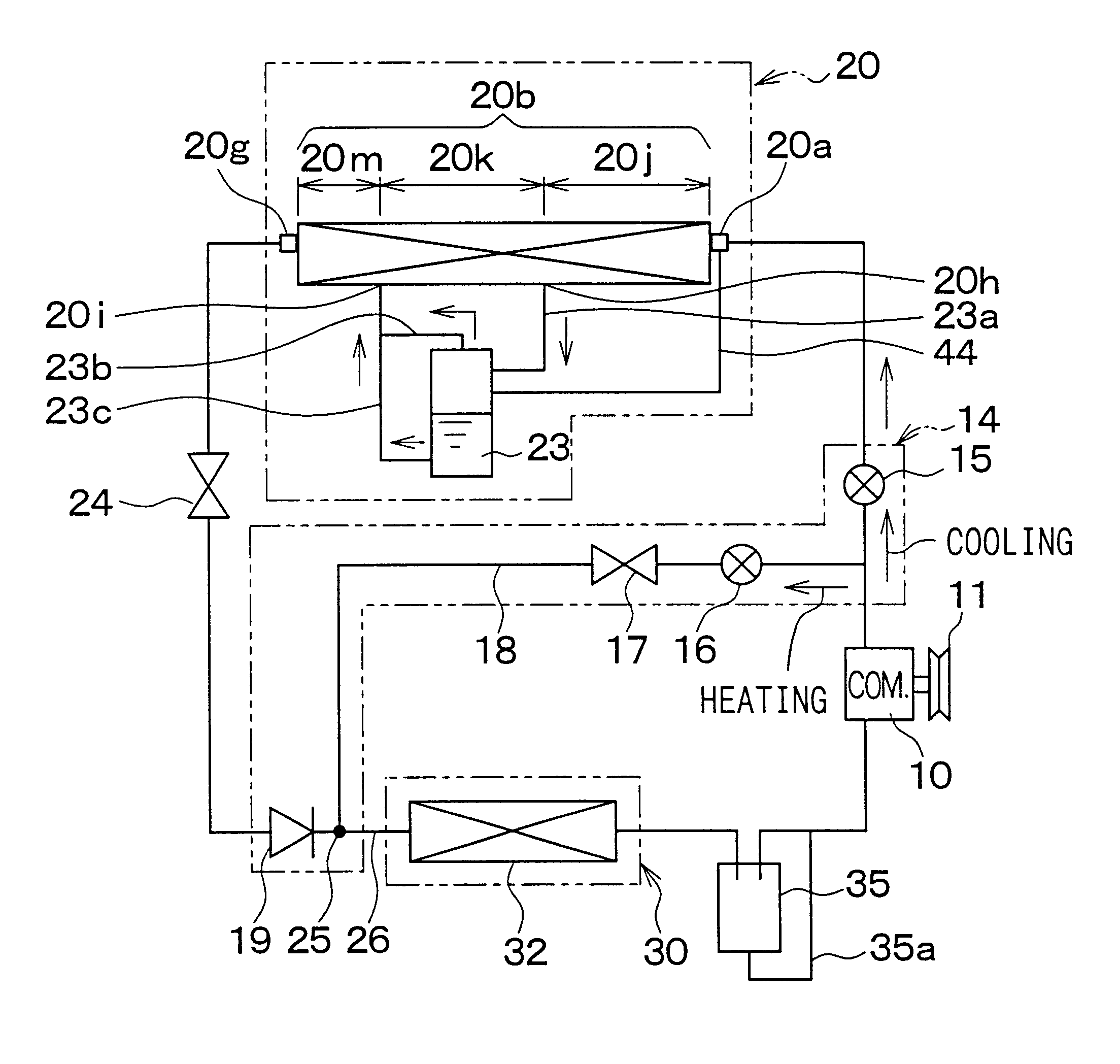
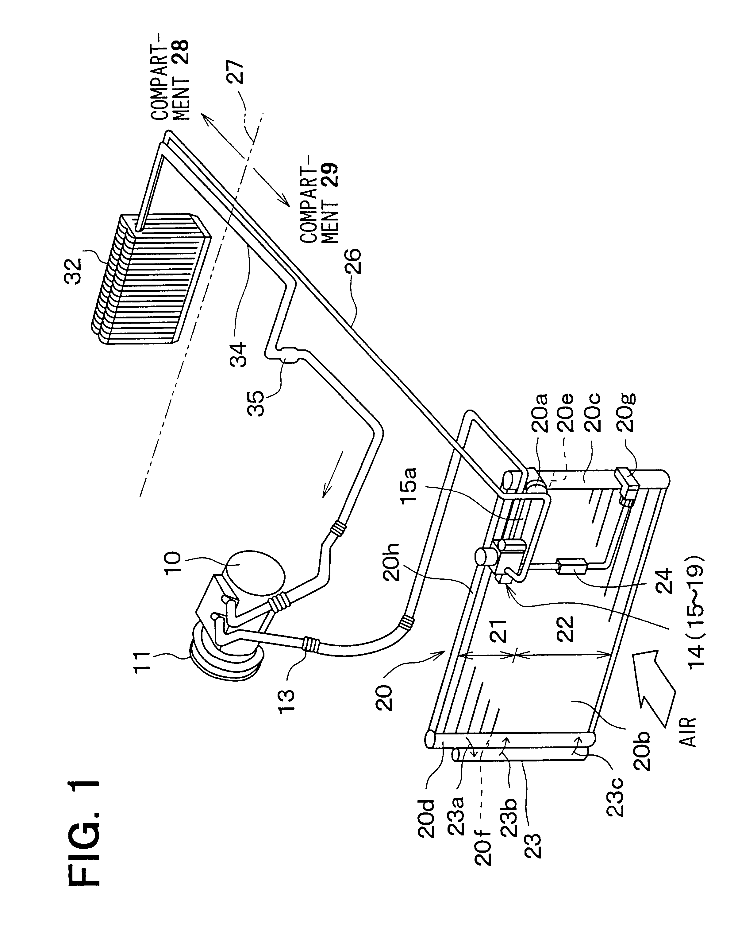
In the first embodiment, the first heat-exchanging unit 21 is constructed in the upper side part of the heat-exchanging portion 20b, and the second heat-exchanging unit 22 is constructed in the lower side part of the heat-exchanging portion 20b. In FIG. 1, for simply indicating the refrigerant flow, the refrigerant flow is indicated in a simple straight line. However, refrigerant may flow meanderingly in the first and second heat-exchanging units 21, 22 of the condenser 20 to be U-turned in at least one of both the header tanks 20c, 20d.

The condenser 20 according to the first embodiment is formed by integrally assembling the first heat-exchanging unit 21, the second heat-exchanging unit 22 and the gas-liquid separator 23 to assemble these three parts into single-piece integrated structure by an aluminum integral brazing method or the like. However, even if these three parts of the first heat-exchanging unit 21, the second heat-exchanging unit 22 and the gas-liquid separator 23 are c...

fourth embodiment

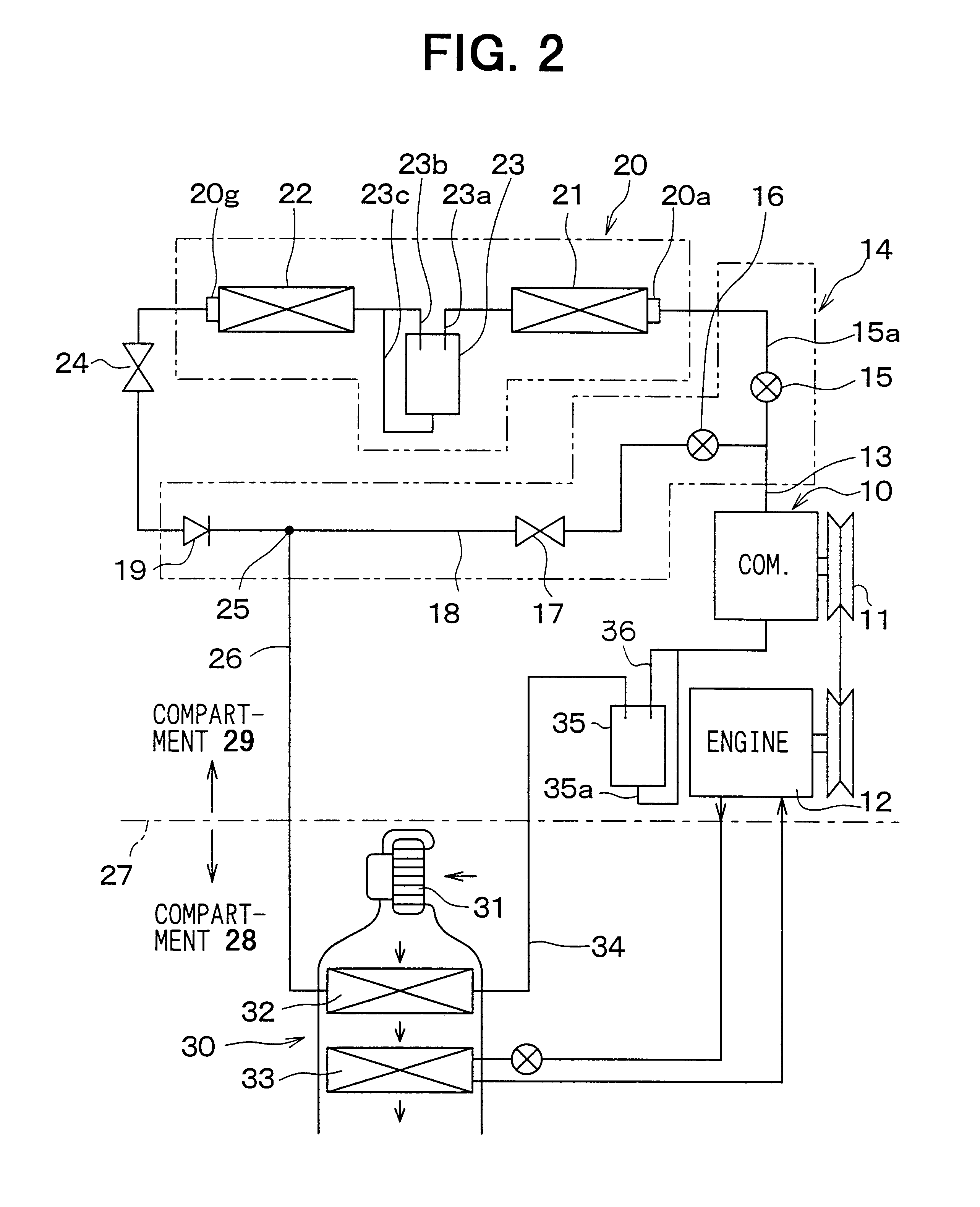
A second communication path 23b, through which gas refrigerant returns from the upper side within the gas-liquid separator 23 into the main refrigerant passage within the condenser 20 at a downstream side, is provided. In addition, a third communication path 23c is provided so that liquid refrigerant containing oil within the gas-liquid separator 23 returns from the lower side within the gas-liquid separator 23 returns to the main refrigerant passage within the condenser 20 at a downstream side. Specifically, both the second and third communication paths 23b, 23c are joined into a single passage, and is connected to the main refrigerant passage of the condenser 20 at a predetermined connection position 20i positioned at a downstream side than the connection position 29h by a predetermined distance. However, in the fourth embodiment, the second communication path 23b and the third communication path 23c may be connected to the main refrigerant passage of the condenser 20, respectivel...

third embodiment

When the accumulator 35 is disposed within the passenger compartment 28 as described in the third embodiment, the accumulator 35 may be integrated with an inner surface of a case of the air conditioning unit 30 or may be integrated with an outer surface of the case of the air conditioning unit 30.

In the condenser 20 of the first embodiment, the first heat-exchanging unit 21, the second heat-exchanging unit 22 and the gas-liquid separator 23 may be integrally connected using a suitable pipe and the like, after being formed respectively separately. Similarly, in the condenser 20 of the second embodiment, the header tank of the condenser 20 and the gas-liquid separator 23 may be integrally connected using a suitable pipe and the like, after being formed respectively separately.

The decompression unit 24 can be constructed by a movable throttle. That is, if the decompression unit 24 is a variable throttle operated in accordance with a refrigerant state (e.g., temperature, pressure) at an...


PUM


Abstract

In a refrigerant cycle system, a low-pressure side gas-liquid separator is disposed between a refrigerant outlet side of an evaporator and a refrigerant suction side of a compressor so that gas refrigerant is sucked into the compressor, and a throttle passage through which liquid refrigerant is introduced into the compressor is disposed in the low-pressure side gas-liquid separator. Further, in a condenser for condensing gas refrigerant discharged from the compressor in a cooling mode, both first and second heat-exchanging units are provided in this order in a refrigerant flow direction, and a high-pressure side gas-liquid separator is disposed between the first and second heat-exchanging units.

Description

1. Field of the InventionThe present invention relates to a refrigerant cycle system for a vehicle, having a hot-gas bypass structure for directly introducing hot gas discharged from a compressor into an evaporator while bypassing a condenser. When the hot-gas refrigerant discharged from the compressor is directly introduced into the evaporator while bypassing the condenser, the evaporator is used as a radiator.2. Description of Related ArtIn a conventional refrigerant cycle system described in U.S. Pat. No. 5,291,941, a hot-gas bypass passage 118, through which refrigerant discharged from a compressor 110 is directly introduced into an evaporator 132 while bypassing a condenser 120, is provided, and a decompression unit 117 is disposed in the bypass passage 118. Further, in an air conditioning unit 130, a heater core 133 is disposed at a downstream air side of the evaporator 132. When temperature of engine-cooling water from an engine 112 is lower than a predetermined temperature i...

Claims


Application Information

Patent Timeline
Patent Type & Authority Patents(United States)
IPC IPC(8): B60H1/00B60H1/32F25B6/00F25B6/04F25B41/04F25B43/00F25B39/04F25B27/00F25B1/00B60H1/22
CPCB60H1/00914B60H1/3227B60H1/323F25B6/04F25B41/04F25B43/006F25B2339/044F25B39/04F25B27/00F25B41/20F25B41/24F25B1/00
Inventor IZAWA, SATOSHITAKANO, YOSHIAKIKUWAHARA, MIKIHARU
Owner DENSO CORP
Why Eureka
Try Eureka