Screw press

Inactive Publication Date: 2003-02-18
AIDA ENG LTD
View PDF20 Cites 34 Cited by
  • Summary
  • Abstract
  • Description
  • Claims
  • Application Information

AI Technical Summary

Benefits of technology

The object of the present invention is to provide a screw press which can ensure the positional precision of the ram when the rotation amount of the above motor does not direct

Problems solved by technology

There are no means for feedback of the actual movement conditions of the ram.
Such devices can obstruct the precision of the ram position because of deformation or loosening.
Stated differently, in the semi-closed loop system of the prior art example, because there is no construction fo

Method used


Image

  • Screw press
  • Screw press
  • Screw press

Examples


Embodiment Construction

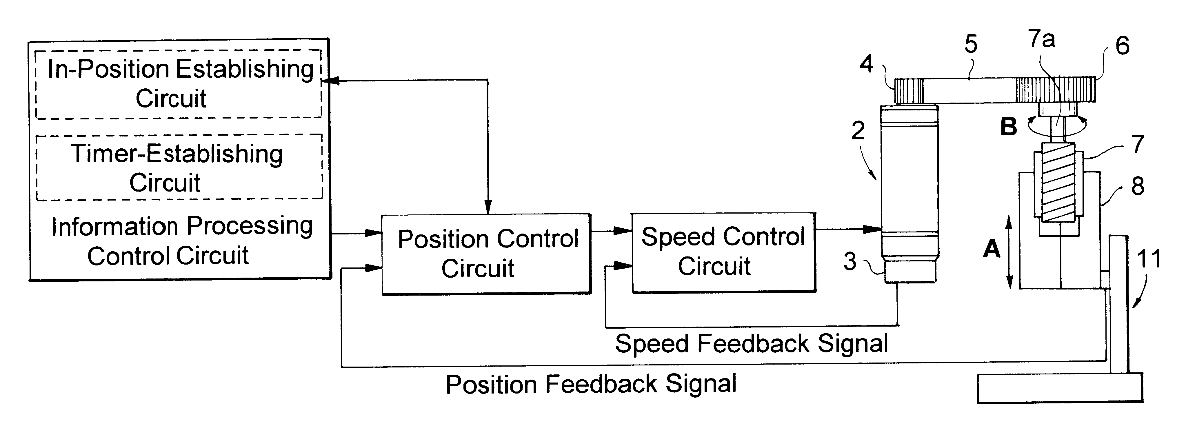
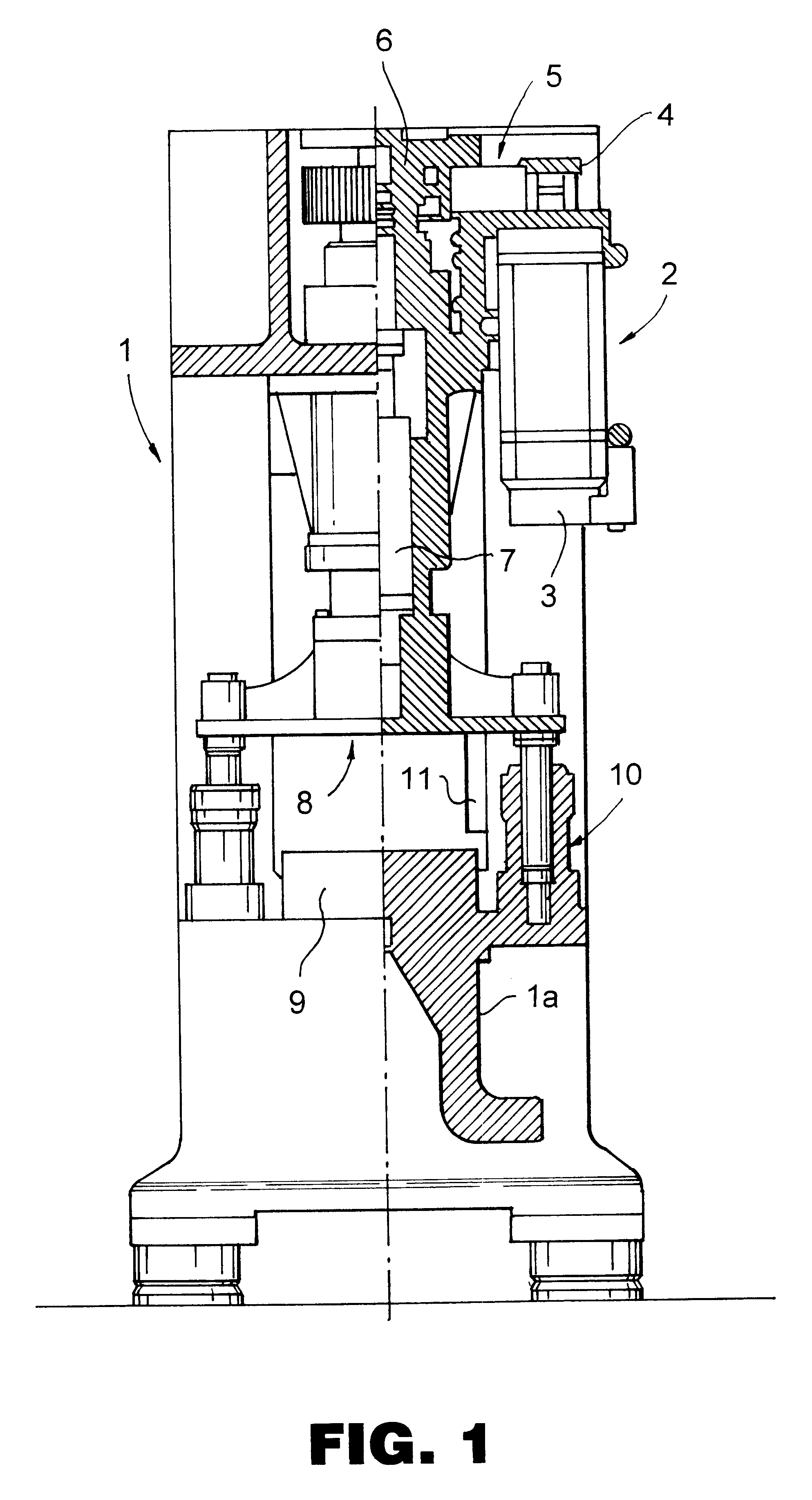
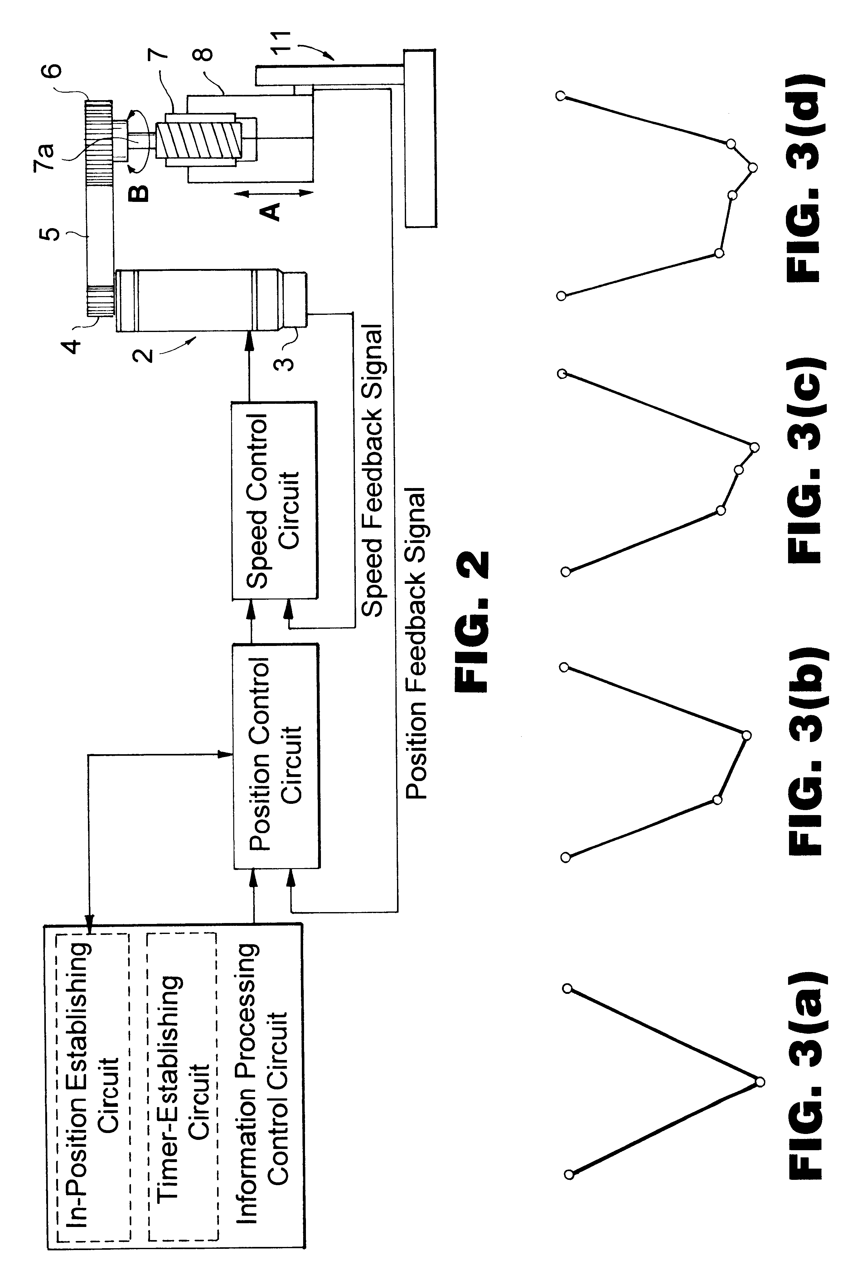
Referring to FIG. 1, a servo motor 2 is affixed to a frame 1. A pulley 4 is affixed to the output shaft of servo motor 2. An encoder 3 is provided on a lower end of servo motor 2. A screw mechanism is provided on frame 1. A pulley 6 is affixed to the top end of the screw shaft. A belt is placed over pulley 4 and pulley 6. The diameter of pulley 4 is smaller than the diameter of pulley 6. The deceleration device is constructed from pulley 4, pulley 6, and belt 5.

The lower end of the above screw shaft is screwed into a nut on a ram 8. Ram 8 is guided by a guide mechanism 10 and can be raised and lowered freely. Guide mechanism 10 comprises a cylindrical guide body affixed to a bed 1a, and a solid rod which is affixed to ram 8 and can be inserted into the above cylindrical guide body. Guide mechanism 10 guides ram 8 in the up and down direction. A bolster 9 is affixed to bed 1a.

Referring to FIG. 1, a linear scale 11 is installed interposed between either frame 1 or bolster 9 and ram 8....


PUM


Abstract

A screw press which can ensure the positional precision of the ram when the rotation amount of the press motor does not directly translate into the position of the ram because there is other machinery, such as a decelerator and the like, present between the motor (servo motor) and the screw mechanism, has a construction in which a position detection sensor, which detects the position of the ram, is provided, and the position of the ram is controlled by the output from this sensor.

Description

BACKGROUND TO THE INVENTIONThe present invention relates to a screw press. A screw press is a press machine which has a servo motor as the driving source and raises and lowers a ram (a slide) by a screw mechanism.U.S. Pat. No. 2,533,486 is an example of the prior art. In the patent publication for this prior art example, there is described a construction in which an electric motor is the drive source and a ram is raised and lowered via a screw mechanism. The position and speed and the like of the ram are controlled using pulses from an encoder which is provided on the motor.Referring to FIG. 5, this prior art is shown. A screw shaft 7a is connected to the output shaft of a motor (servo motor) 2. An end of screw shaft 7a is screwed into a nut 8a of a ram 8. When servo motor 2 rotates in the direction of arrow B, ram 8 is raised and lowered in the direction of arrow A due to the action of a screw mechanism 7. In other words, when there is positive rotation and reverse rotation of serv...

Claims


Application Information

Patent Timeline
IPC IPC(8): B30B1/00B30B1/18
CPCB30B1/186
Inventor MINAGAWA, TAKAKIOYAMADA, YASUHIKOSUZUKI, KUNIHIROKUBOTA, YOUICHI
Owner AIDA ENG LTD
Why Eureka
Try Eureka