Electro-optical device and method for driving the same, liquid crystal device and method for driving the same, circuit for driving electro-optical device, and electronic device

a technology of electrooptical devices and liquid crystal devices, applied in the direction of instruments, static indicating devices, etc., can solve the problems of non-display state, power consumption that has not been expectedly reduced, and power consumption that has not been realized to date, so as to achieve a great reduction of power consumption and improve general usability

Inactive Publication Date: 2003-02-18
138 EAST LCD ADVANCEMENTS LTD
View PDF13 Cites 118 Cited by
  • Summary
  • Abstract
  • Description
  • Claims
  • Application Information

AI Technical Summary

Benefits of technology

To these ends, an object of the present invention is to solve the problems with the conventional art and is to provide an electrooptical apparatus allowing great reduction of power consumption. It is another object to provide an electr...

Problems solved by technology

Accordingly, power consumption by the display apparatus is also increasing.
In conventional liquid crystal display apparatuses, they have, in most cases, a function allowing control of display/non-display operations on a full-screen basis; however, a display apparatus having a function that allows only part of a full screen to be in a display state and allows the other to be in a non-display state has not been realized to date.
In this case, a defect is caused such as that even after the screen turned to be in the partial display state, circuits such as drivers would still continue to operate, and charging and discharging of the liquid crystal would still continue; therefore, power consumption is not expectedly reduced.
This is caused by the fact that time when selection voltages are added to the liquid crystal is duplicated to excessively increase effective voltages.
It is very inconvenient for apparatus users.
Supplement of a driving-voltage automatic setting means is mandatory; however, it is not so easy as a bias-ratio switching means and the driving-voltage forming circuit will be much complicated.
However, since a large volume of the reduction voltage of 8 V is consumed to allow the contrast-adjustment transistor Q1 to generate heat, the power consumption is not reduced so much.
However, there still remains problems such as that a driving-voltage forming circuit will be very complicated, th...

Method used


Image

  • Electro-optical device and method for driving the same, liquid crystal device and method for driving the same, circuit for driving electro-optical device, and electronic device
  • Electro-optical device and method for driving the same, liquid crystal device and method for driving the same, circuit for driving electro-optical device, and electronic device
  • Electro-optical device and method for driving the same, liquid crystal device and method for driving the same, circuit for driving electro-optical device, and electronic device

Examples


second embodiment

Next, this embodiment will be described with reference to drawings 5 and 6. FIG. 5 is a circuit diagram showing part of the controller 5 in FIG. 1, which is a circuit block that controls the partial display state. FIG. 6 is a drawing showing timing charts that describe performance of the circuit in FIG. 5, and it is a supplemental and enlarged drawing showing part of the timing charts in FIG. 3 for the first embodiment. Construction and performance of a liquid crystal display apparatus of this invention is the same as those of the first embodiment described above. Therefore, descriptions regarding the same portions as those of the first embodiment will be omitted.

First, a circuit construction in FIG. 5 will be described. The numeral 14 denotes a register of 8 bits or the like, in which there are defined information on whether or not a display state is a partial display state and defied information corresponding to the number of lines to be displayed. When the number of the lines are...

third embodiment

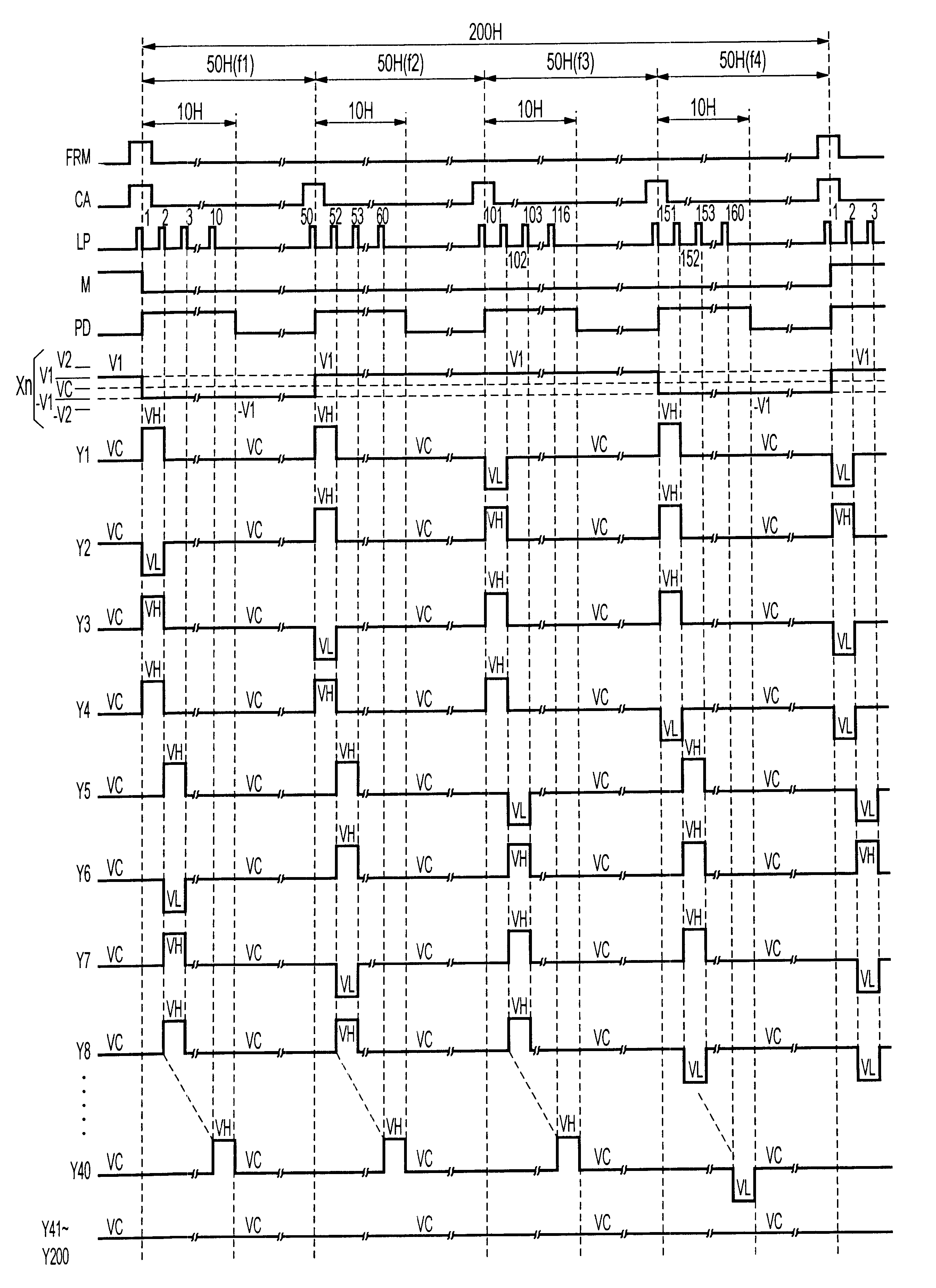
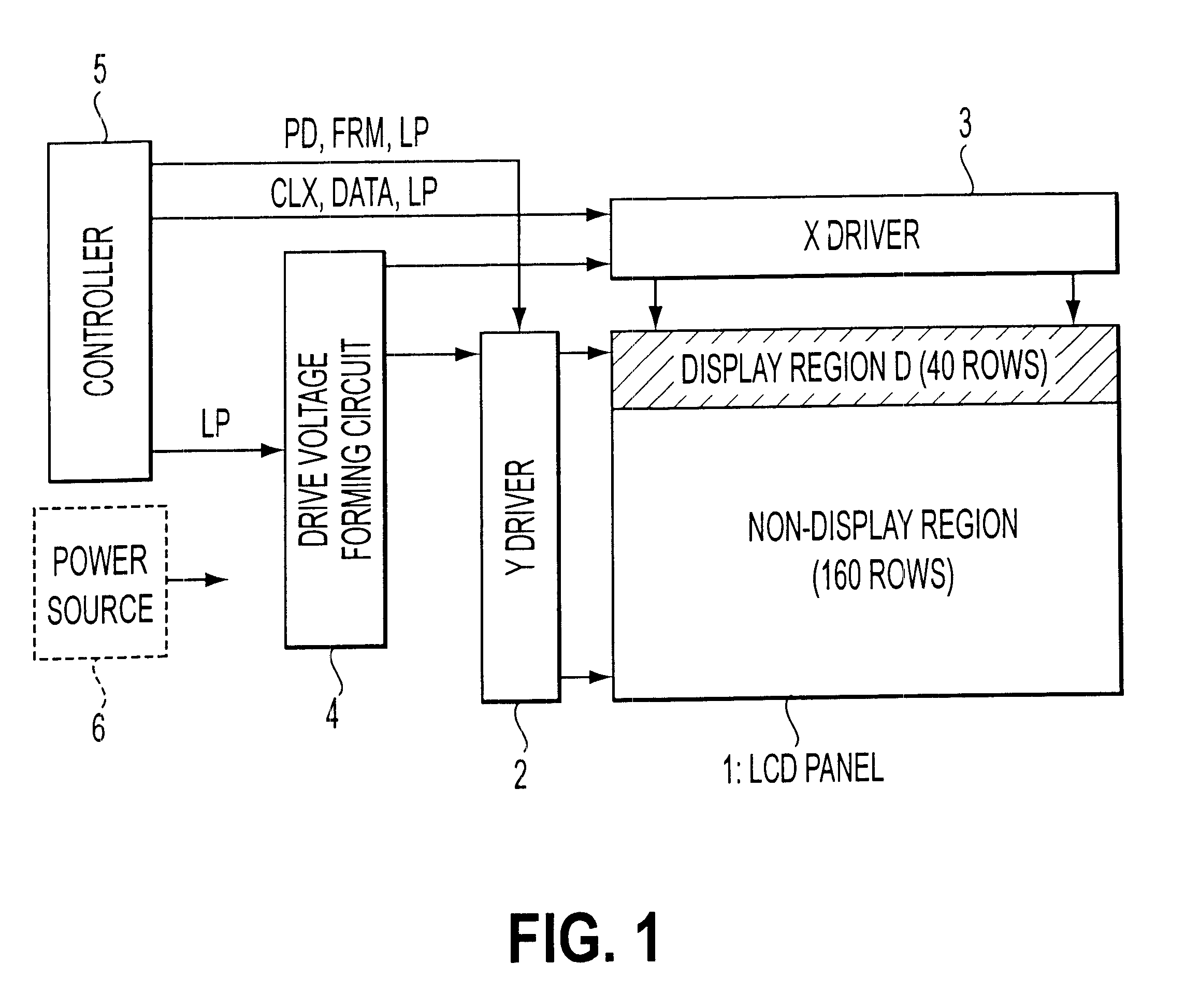
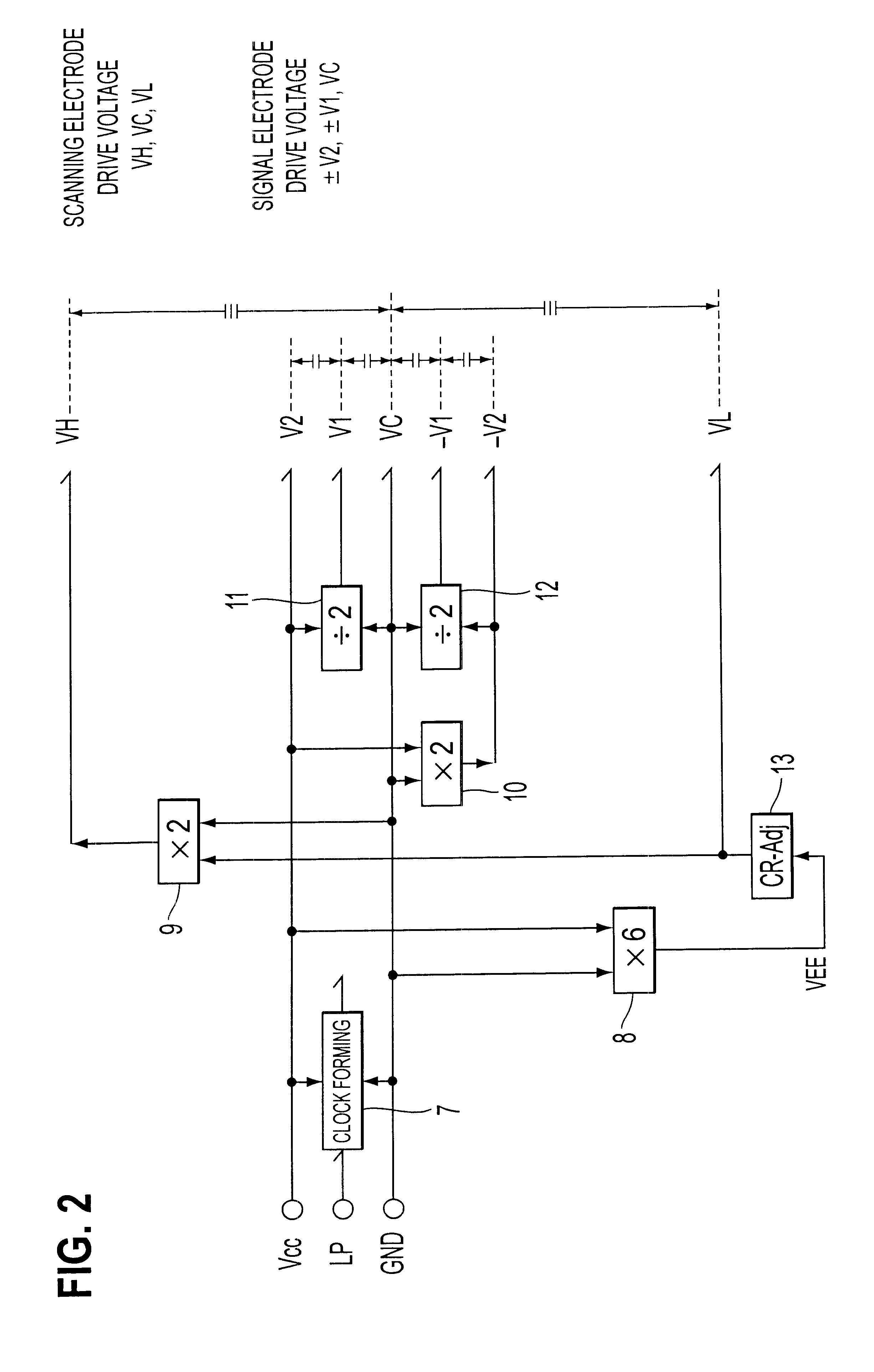
This embodiment is different from the first embodiment only in an aspect in which potentials of signal electrodes in the non-display-line access period are fixed at the same levels of those in the case of full-screen OFF display. This embodiment is the same as the first embodiment in that it adopts the 4MLS driving method of the selection-voltage equal distribution type using the Corn pattern in FIG. 4A, and as shown in FIG. 2, the driving-voltage forming circuit 4 mainly constituted of the charge-pump circuit; a full screen has 200 lines of the scanning electrodes and only 40 of the 200 lines are in the display state; it is an example case in which the horizontal line is displayed at every other scanning electrode in the display state portions; the length of the one-frame period is 200 H; the application voltage for the scanning electrodes in the non-display-line access period is fixed at the non-selection voltage VC; and the polarity of the liquid-crystal driving voltage is invert...

fourth embodiment

Hereinbelow, a description will be given of an example case when an SA (smart-addressing) driving method is used to perform the partial display. Construction of the liquid crystal display apparatus is the same as that in FIG. 1 already described. In FIG. 20 showing the conventional driving voltage waveforms, the SA driving method is a driving method in which, for example, the liquid-crystal alternating-current driving signal M entirely reduces driving potentials (V1 to V4) in the H period as much as possible to turn the non-selection voltages to one level, and the scanning electrodes are sequentially selected one by one as in the same case of the conventional driving. First, a description will be given of an example of a driving-voltage forming circuit equivalent to the block 4 in FIG. 1, with reference to FIG. 8, which is a block diagram thereof.

In the same way as in case of the MLS driving method, the SA driving method requires three voltage levels, which are the non-selection vol...


PUM


Abstract

In an electrooptical apparatus having a function allowing part of a display screen to be in a display state and allowing the other to be in a non-display state, for a non-display region, application voltages for scanning electrodes are fixed at non-selection voltages, and application voltages for signal electrodes are fixed at voltages similar to the case of a full-screen ON-display or a full-screen OFF-display at least in a predetermined period; therefore, power consumption in the partial display state can be reduced.

Description

1. Field of the InventionThe present invention relates to an electrooptical apparatus having a function causing a part of a display screen to be in a display state and causing the other to be in a non-display state and a driving method therefor. Furthermore, the invention, using a liquid crystal display apparatus as the electrooptical apparatus, relates to the driving method for the liquid crystal display apparatus, which allows a partial display state without providing an incompatibility and with less power consumption, and it also relates to the liquid crystal display apparatus performing display operation according to the above. The present invention also relates to a driving circuit suitable for driving the electrooptical apparatus of the invention.Furthermore, this invention relates to an electronic equipment to be used for the electrooptical apparatus and the display apparatus described above.2. Description of Related ArtWith display apparatuses being used for portable electro...

Claims


Application Information

Patent Timeline
IPC IPC(8): G09G3/36G09G3/20
CPCG09G3/20G09G3/36G09G3/3622G09G3/3644G09G3/3666G09G3/3681G09G3/3692G09G3/3696G09G2360/18G09G3/3648G09G3/367G09G2310/04G09G2310/06G09G2320/0247G09G2330/021G09G2330/028G09G3/2092
Inventor YAMAZAKI, SUGURU
Owner 138 EAST LCD ADVANCEMENTS LTD
Why Eureka
Try Eureka