Magnetic coupling pump

a coupling pump and magnetism technology, applied in the direction of pump, positive displacement liquid engine, liquid fuel engine, etc., can solve the problems of restricting the detection accuracy the sensitive thermal etc., to suppress thermal damage, reduce the damage of the magnetism detecting element, and suppress the effect of thermal damag

Inactive Publication Date: 2003-02-25
AISAN IND CO LTD
View PDF8 Cites 44 Cited by
  • Summary
  • Abstract
  • Description
  • Claims
  • Application Information

AI Technical Summary

Benefits of technology

In the above-mentioned manner, the annular-shaped wall portion is made thin in wall thickness, whereby the exothermic electronic parts are efficiently cooled by a cooling water, thus enabling suppressing thermal damage, which the magnetism detecting element suffers from heat generated by the exothermic electronic parts.
Also, the magnetism detecting element and the exothermic electronic parts, respectively, are arranged in substantially opposite positions in the substantially annular-shaped area of the circuit board, so that a spacing between the magnetism detecting element and the exothermic electronic parts becomes large to enable suppressing thermal damage, which the magnetism detecting element suffers from heat generated by the exothermic electronic parts.
Also, the circuit board can be made to approach the annular-shaped wall portion by a distance corresponding to reduction in wall thickness of the annular-shaped wall portion, with the result that a distance from the magnetism detecting element to an end surface of the annular-shaped wall portion on the side of the motor chamber becomes small and so a spacing between the annular-shaped end surface of the rotor and the magnetism detecting element decreases. Therefore, the magnetism detecting element is increased in detection level to be enhanced in accuracy of detection.

Problems solved by technology

However, with a magnetic coupling pump of the above-mentioned type, in which both the above exothermic electronic parts and the above magnetism detecting element are mounted on a circuit board, the exothermic electronic parts and the magnetism detecting element are arranged comparatively close to each other, so that the magnetism detecting element is susceptible to thermal damage from the exothermic electronic parts.
Also, since the exothermic electronic parts are larger in thickness than the magnetism detecting element, an air gap between the magnetism detecting element and a partition is comparatively large, which restricts detection accuracy of the magnetism detecting element.

Method used


Image

  • Magnetic coupling pump
  • Magnetic coupling pump
  • Magnetic coupling pump

Examples


Embodiment Construction

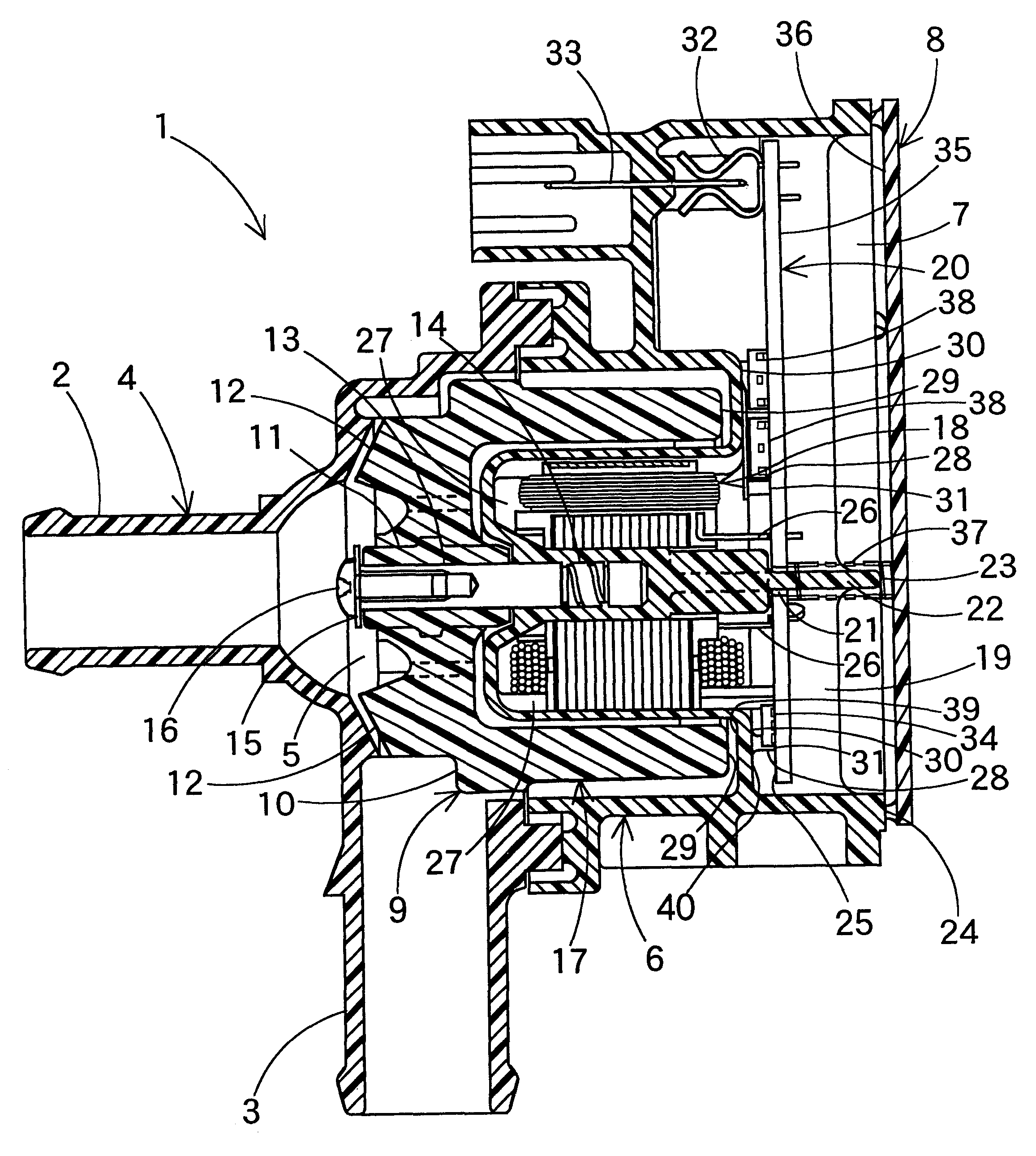
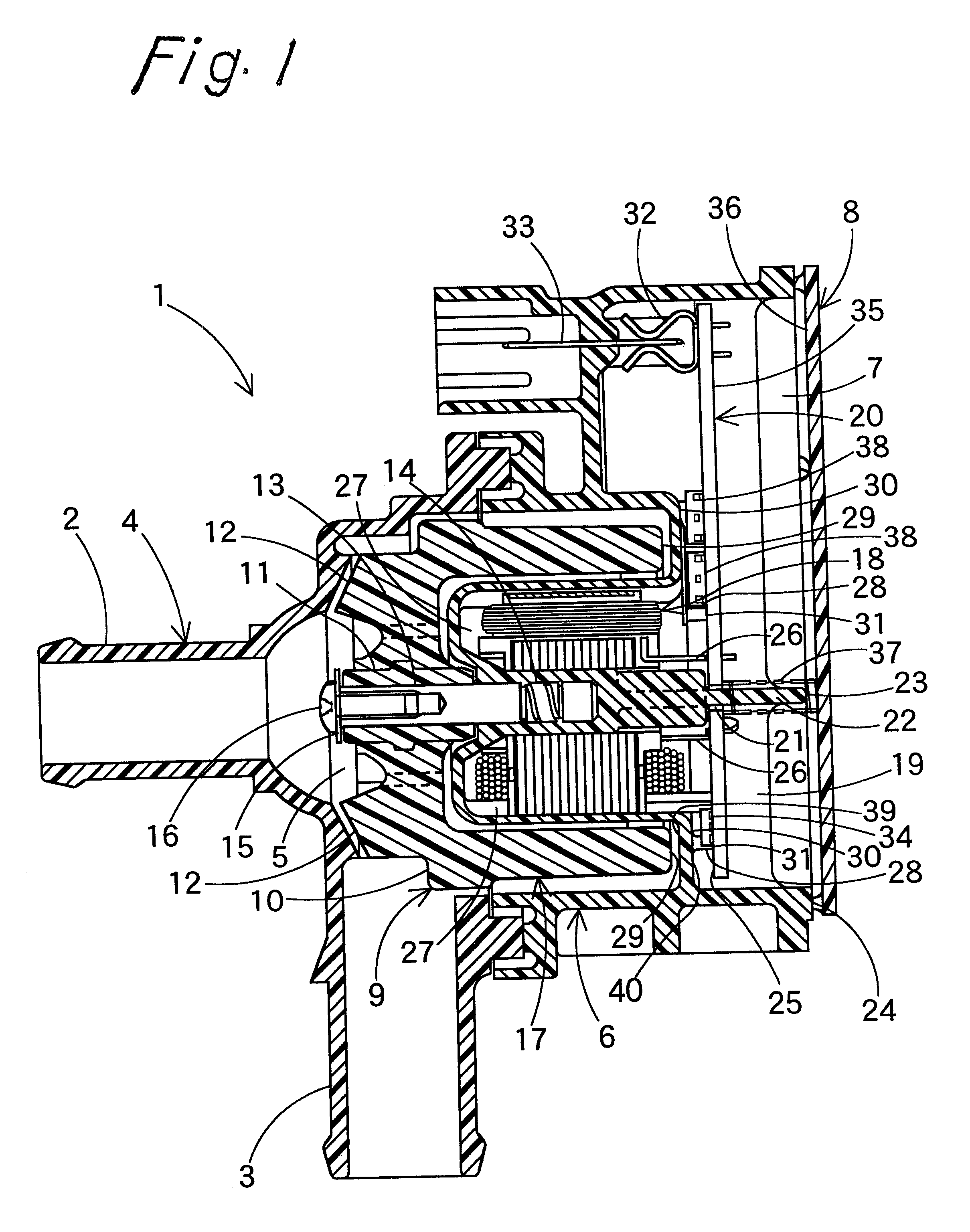
In FIG. 1, a magnetic coupling pump 1 comprises a pump chamber side housing 4 made of a synthetic resin and formed with an inflow passage 2 for a cooling water and an outflow passage 3, a body 6 made of a synthetic resin and cooperating with the pump chamber side housing 4 to define a pump chamber 5, and a motor chamber side housing 8 made of a synthetic resin and cooperating with the body 6 to define a motor chamber 7. The pump chamber side housing 4 and the body 6, and the body 6 and the motor chamber side housing 8 are fused to each other to be made integral.

A rotor 9 made of a synthetic resin is contained in the pump chamber 5.

The rotor 9 is formed to be substantially cylindrical-cup shaped, and formed centrally of a bottom 10 thereof with a cylindrical-shaped bearing 11 of PPS (polyphenylene sulfide) material, the bearing 11 being formed therearound with an impeller 12. A shaft 13 is inserted through a through hole of the bearing 11, and the rotor 9 is made rotatable about the ...


PUM


Abstract

A partition partitions off a motor chamber and a pump chamber, through which a cooling water flows, a substantially cylindrical-cup shaped rotor is arranged in the pump chamber, a circuit board is disposed in the motor chamber to be in parallel to an annular-shaped end surface of the rotor, a magnetism detecting element is mounted on that portion of the circuit board, which faces a magnet portion of the rotor, and exothermic electronic parts are mounted on the remaining portion of the circuit board. The magnetism detecting element and the exothermic electronic parts, respectively, are arranged in opposite positions in a substantially annular-shaped area of the circuit board, which faces the annular-shaped end surface of the rotor, and a thickness of an annular-shaped wall portion of the partition facing the annular-shaped end surface of the rotor is made thin in a portion adjacent to the exothermic electronic parts on condition that an annular-shaped surface of the annular-shaped wall portion on a side of the annular-shaped end surface of the rotor is a non-inclined flat surface.

Description

(1) Field of the InventionThe invention relates to a magnetic coupling pump, and more particularly, to a magnetic coupling pump, used as a water pump, to contemplate enhancement of cooling efficiency for exothermic electronic parts mounted on a circuit board as well as improvement of detection accuracy of a magnetism detecting element mounted on the circuit board.(2) Description of the Prior ArtAs is well-known, a magnetic coupling pump used as a water pump is constructed such that a partition partitions off a motor chamber and a pump chamber, through which a cooling water flows, a rotor is disposed in the pump chamber, and a stator (motor) is disposed in the motor chamber.As an example of conventional magnetic coupling pumps, there has been known a magnetic coupling pump, as disclosed in FIG. 2 of Japanese Patent Laid-Open No. 311290 / 1998, constructed such that a circuit board is disposed in a motor chamber to be in parallel to an end surface of a rotor, exothermic electronic parts...

Claims


Application Information

Patent Timeline
Patent Type & Authority Patents(United States)
IPC IPC(8): F04D13/06F04D13/02F04D29/58
CPCF04D13/0686F04D13/064
Inventor DEAI, JUNJIITOU, HIROHISA
Owner AISAN IND CO LTD
Why Eureka
Try Eureka