Method of making a physically and chemically active environment by means of a plasma jet and the related plasma jet

a plasma jet and environment technology, applied in the direction of chemical vapor deposition coating, coating, electric discharge lamps, etc., can solve the problems of limited use of methods, two methods are limited to low pressure, and limited to low pressur

Inactive Publication Date: 2003-02-25
MASARYK UNIVERSITY
View PDF10 Cites 64 Cited by
  • Summary
  • Abstract
  • Description
  • Claims
  • Application Information

AI Technical Summary

Problems solved by technology

The use of the method is only limited to low pressures, a gaseous working medium and an external plasmatic environment.
These two methods are only limited to low pressures, a gaseous working medium and an external plasmatic environment.
The main drawback of the above methods and equipment for their performance is the fact that they are only limited to low pressures

Method used


Image

  • Method of making a physically and chemically active environment by means of a plasma jet and the related plasma jet
  • Method of making a physically and chemically active environment by means of a plasma jet and the related plasma jet
  • Method of making a physically and chemically active environment by means of a plasma jet and the related plasma jet

Examples


example 1

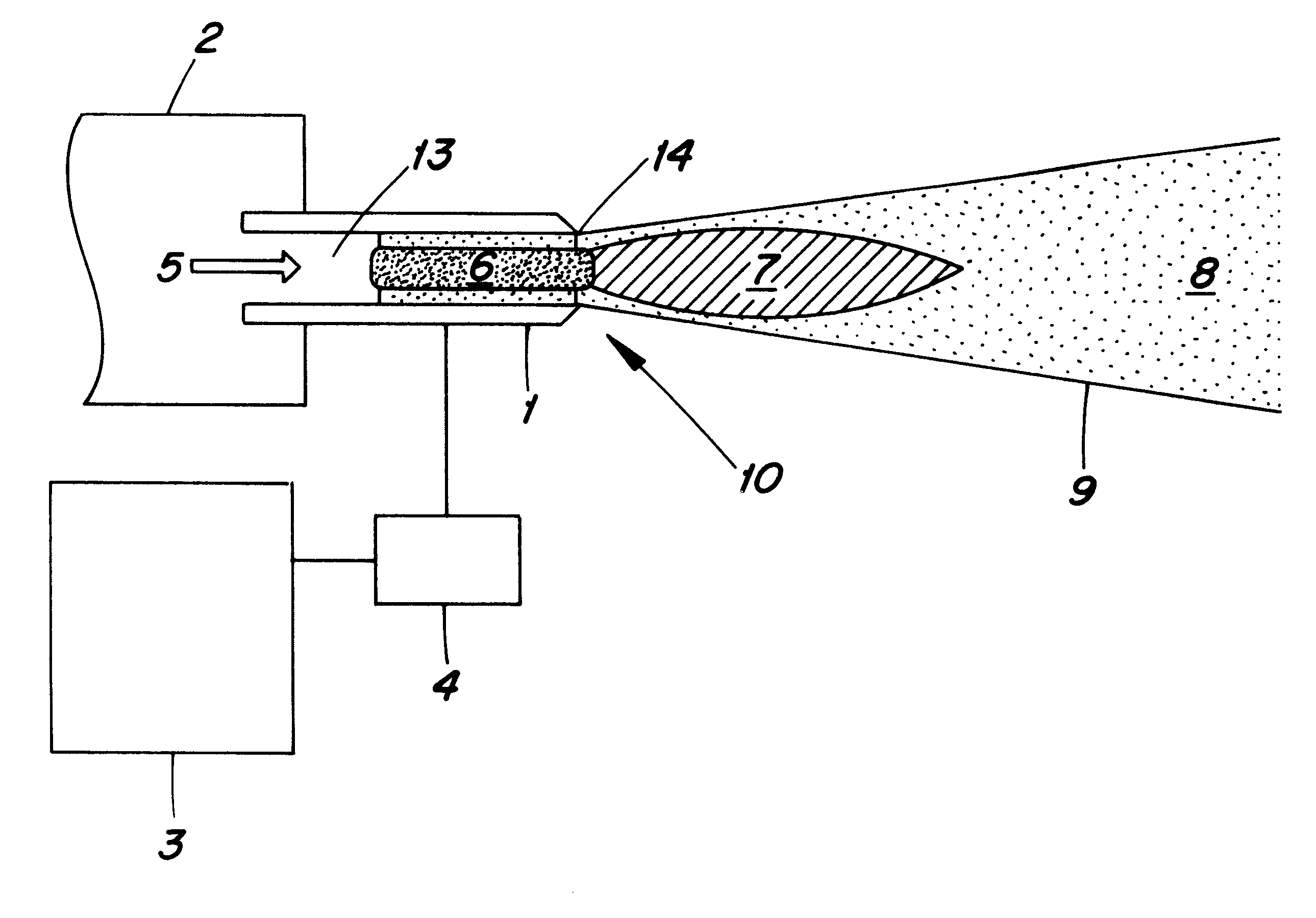
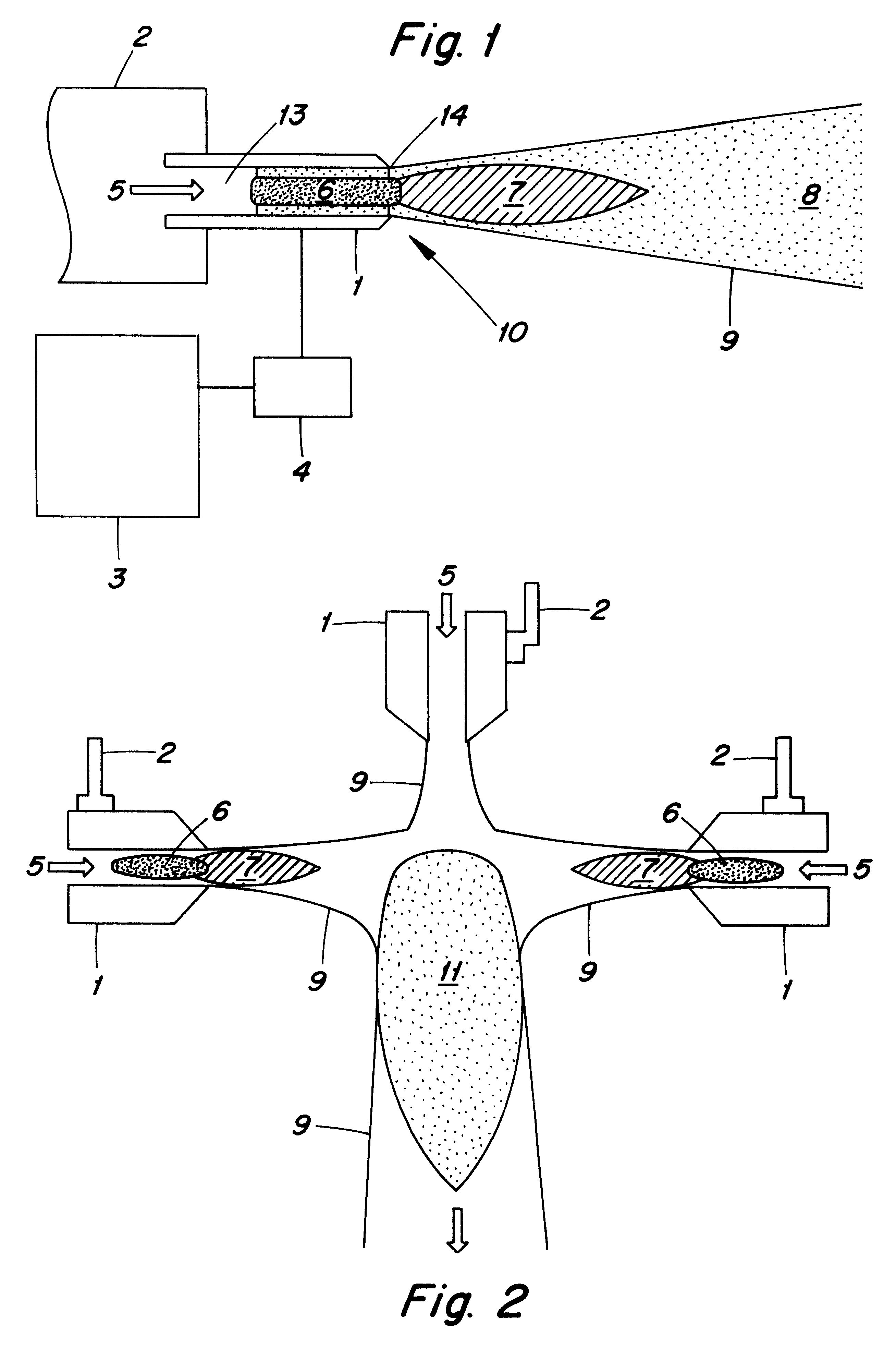
The simplest design variant put in effect of the plasma jet is represented in FIG. 1 for the case in which the ambient environment of the plasma jet is in the gaseous or plasmatic state, at the pressure higher than about 10.sup.3 Pa, and / or in free atmosphere or at a pressure higher than the atmospheric pressure. Electrode 1 is in the form of a hollow cylinder with a conical narrowing, with element 14 locally increasing the density of electromagnetic energy, constituted by the sharpened edges of the cavity orifice 13 of electrode 1. This type is preferably employed in a system with an external counterelectrode or it serves as physical element 17 for the generation of the discharge inside cavity 13 and further electrode 1.

To the hollow electrode 1 through which the working gas 5 flows is, via the impedance adapting member 4 consisting of a system of regulatory, transformation and transmitting elements, attached a ss, nf, hf or vhf source 3. The hollow electrode 1 is fixed to a motile...

example 2

The plasma jet represented in FIG. 2 consists of a system of hollow electrodes 1, of which at least one is the source of physically and chemically active environment and at least one is mechanically or directly manually controllable by means of the holder 2.

On the basis of a conflict of two and more reaction channels 9 from the individual hollow electrodes 1 a resultant reaction channel 11 arises with formations of streaming plasma (usually much more voluminous then the primary reaction channels) which newly or further activated the fed working medium 5.

example 3

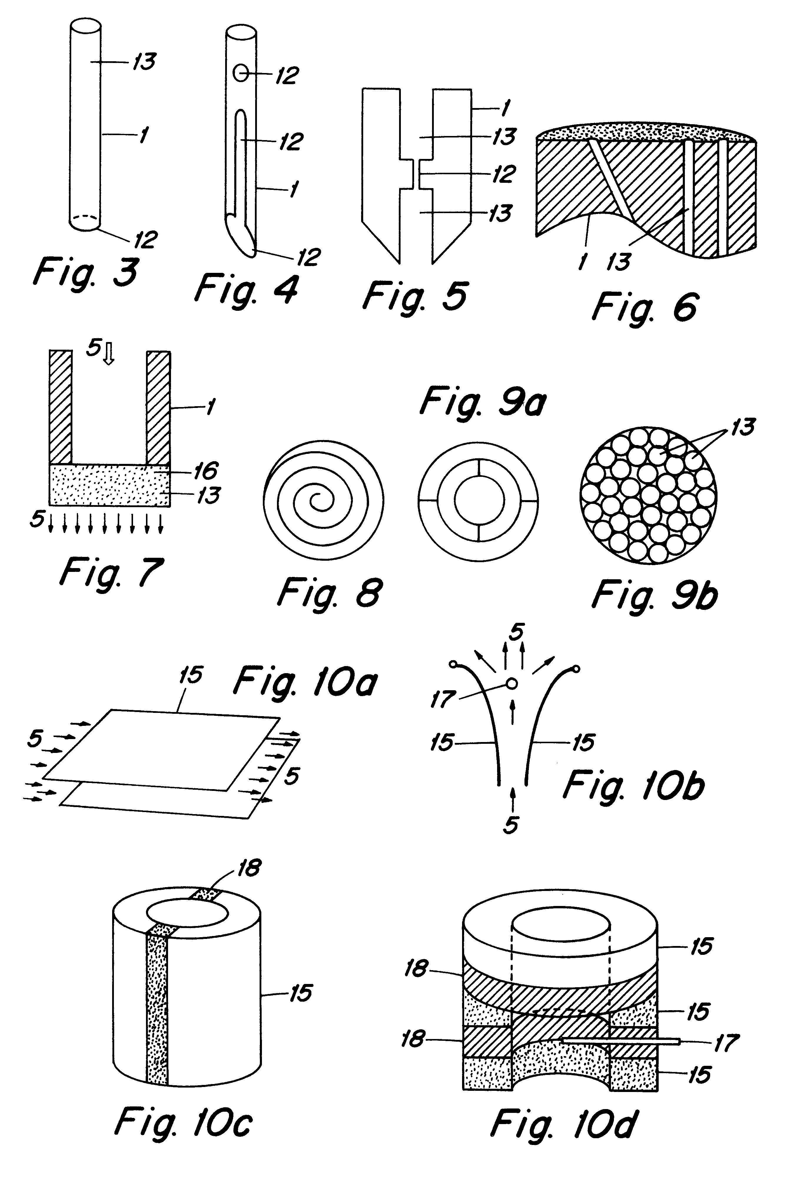
FIG. 11 represents a schematic drawing of the plasma jet, when the material of the electrode 1 is cooled by the streaming medium 5 which is advantageously utilised after fulfilling its cooling function to the subsequent activation in some of the domains of physically and chemically activated environment 6 and 7, or it is utilised for modelling the shape of the reaction channel 9.

A part of the plasma jet of all above variants can be a permanent magnet 20 and / or an electromagnet or their system located outside the plasma jet (FIGS. 13a-c) which participates in the formation and controls the process of plasma generation.


PUM

PropertyMeasurementUnit
Pressureaaaaaaaaaa
Magnetic fieldaaaaaaaaaa
Densityaaaaaaaaaa

Abstract

The method consists in the fact that from at least one external source (3) electromagnetic energy is conducted to at least one hollow electrode (1) with elements (14) locally increasing the density of electromagnetic energy, by which, inside the cavities of the electrode (1) and/or at its orifice and in the external environment an intensive discharge is generated. The plasma jet consists of at least one hollow electrode (1) of conductive or conductive and dielectric material with at least one element (14) locally increasing the density of electromagnetic energy inside the hollow electrode (1) and/or at its orifice and/or outside, which consists of a design element (12) and/or a physical element (17) acting in the transversal and/or the longitudinal direction with respect to the streaming working medium (5) and is further constituted by at least one source (3) or electromagnetic energy attached via the impedance adapting member (4) consisting of a system of regulatory transformation and transfer elements, onto the conductive part of the hollow electrode (1).

Description

FIELD OF TECHNOLOGYThe invention concerns the method of making a physically and chemically active environment by means of a plasma jet which permits the transformation and the oriented transfer of electromagnetic energy in its different forms by means of a plasma, from the plasma jet to the treated object.BRIEF DESCRIPTION OF THE RELATED ARTFor making a physically and chemically active environment utilised for the treatment of objects or chemical compounds currently a broad spectrum of discharges generated in different ways on the basis of electromagnetic energy are used which in turn affect the activated medium or directly the treated objects.From CZ 246982 a method of spatially oriented chemical activation of the working gas by plasma is known in the region between the jet attached via the adapting member to the source of high-frequency (hf) energy with a non-symmetric output and the earthed electrode attached to the second output of the above source. The use of the method is only...

Claims


Application Information

Patent Timeline
IPC IPC(8): H05H1/26H05H1/30H05H1/24H05H1/34
CPCH01J37/321H05H1/30H01J37/3266H01J37/32623
Inventor KLIMA, MILOSJANCA, JANKAPICKA, VRATISLAVSLAVICEK, PAVELSAUL, PETR
Owner MASARYK UNIVERSITY
Why Eureka
Try Eureka