Frame kit for PC card, PC card, and method of manufacturing PC Card

a technology of pc card and frame kit, which is applied in the field of pc card frame kit, pc card and pc card production method, can solve the problems of pc card becoming disassembled, falling short of product perfection, and loose connection between metal panels and the fram

Inactive Publication Date: 2003-03-04
JST MFG CO LTD
View PDF20 Cites 50 Cited by
  • Summary
  • Abstract
  • Description
  • Claims
  • Application Information

AI Technical Summary

Benefits of technology

It is an object of the present invention to provide a PC card frame kit which provides a PC card free from any looseness, and to provide a PC card utilizing such a PC card frame kit.
Since the press-fit pieces of the respective panels are press-fitted in the press-fit groove of the frame, the PC card thus produced is free from any looseness, and has a higher resistance to an external force.

Problems solved by technology

However, this arrangement inevitably entails a loose connection between the metal panels and the frame.
The loose connection practically presents no functional problem, but the PC card is mechanically unstable, thereby falling short of product perfection.
In addition, the PC card may become disassembled if a great shock is applied thereto, for example, when the card is dropped on the floor.
However, the prior art approach fails to assuredly prevent the disassembly of the PC card which may occur if a great shock is applied to the card, for example, when the card is dropped on the floor, because the looseness occurs within the range of resilient deformation of the resilient press members.
Therefore, the PC card is not satisfactory in terms of product perfection.
However, the positioning of the panels with respect to the frame is not necessarily easy, resulting in difficulty in the assembling.
This leads to a lower PC card assembling efficiency.

Method used


Image

  • Frame kit for PC card, PC card, and method of manufacturing PC Card
  • Frame kit for PC card, PC card, and method of manufacturing PC Card
  • Frame kit for PC card, PC card, and method of manufacturing PC Card

Examples


Embodiment Construction

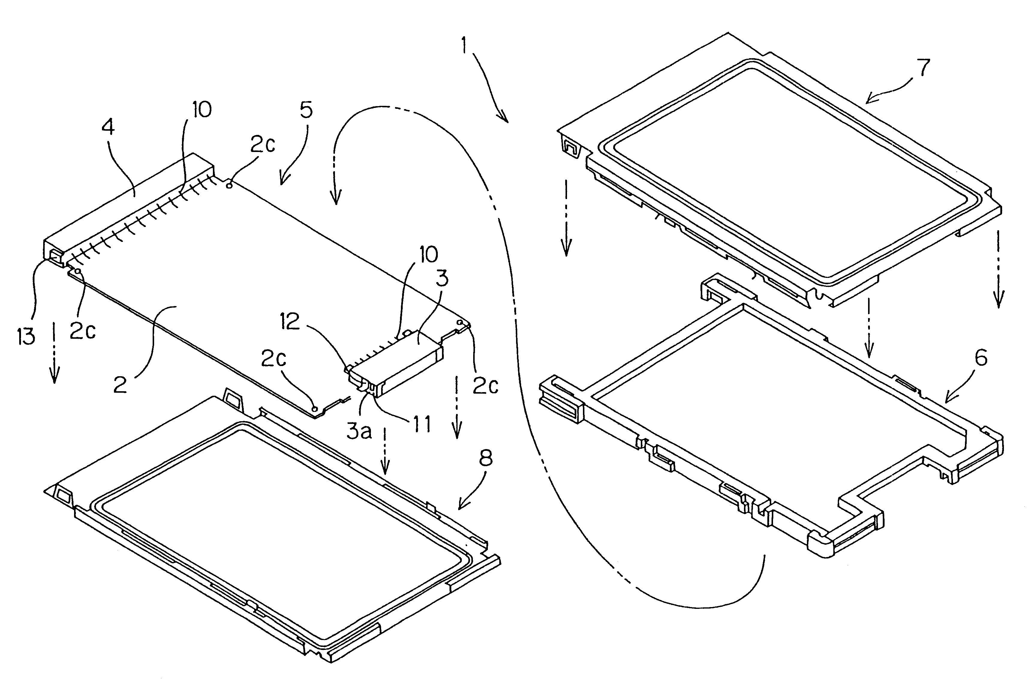
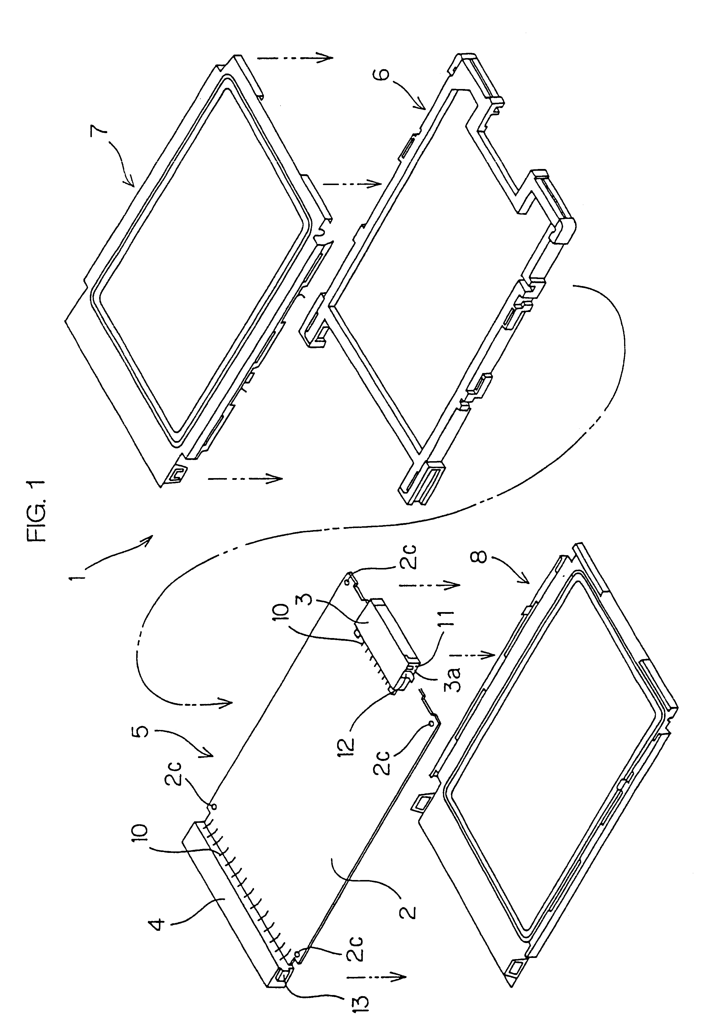
FIG. 1 is an exploded perspective view illustrating the construction of a PC card 1 according to one embodiment of the present invention. Referring to FIG. 1, the PC card 1 includes a printed board 2, connectors 3, 4 mounted on the printed board 2, a frame 6 retaining a board assembly 5 having the first and second connectors 3, 4 mounted on front and rear edges of the printed board 2, and a pair of metal panels 7, 8 covering upper and lower faces of the board assembly 5 mounted in the frame 6.

The first connector 3 is used for electrical connection between the printed board 2 and an external connector (not shown), while the second connector 4 is used for electrical connection between a PC card slot (not shown) and the printed board 2. In the following explanation, the side of the second connector 4 to be connected to the PC card slot is regarded as the front side, and the side of the first connector 3 is regarded as the rear side.

The printed board 2 has a cutaway portion (not shown) ...


PUM


Abstract

A PC card frame kit is provided which comprises: a frame for retaining a board assembly having a connector mounted on a board; and a pair of panels for covering upper and lower faces of the board assembly mounted in the frame. The pair of panels each have a pivotal engagement piece provided on a rear edge thereof for pivotal engagement with the frame, front lock engagement pieces provided on front ends of opposite side edges thereof for lock engagement between the panels, and a press-fit piece provided on at least one of the side edges thereof to be press-fitted in the frame. The frame has a pivotal engagement piece receiving groove formed in a rear beam thereof for receiving the pivotal engagement piece in a rotatable manner, and a press-fit groove formed in at least one of opposite side beams associated with the press-fit piece for receiving the press-fit piece.

Description

TECHNICAL FIELDThe present invention relates to a PC card frame kit, a PC card and a PC card production method. The term "PC card" is herein to be understood to include PC cards in a narrow sense, cards for communications such as memory cards and LAN cards, smart cards, small PC cards, CF (compact flash (trade mark)) cards, and other cards having constructions similar to the PC cards in a narrow sense.BACKGROUND ARTNotebook personal computers, for example, are typically provided with a PC card slot, in which a PC card is fitted for extension of their capabilities. The PC card is of a card shape as a whole, and includes a board assembly having a connector mounted on a board for connection to the PC card slot, a frame retaining the board assembly, and a pair of metal panels covering upper and lower surfaces of the board assembly.PC card production processes are generally classified into a mechanical production process which is suitable formass production and a manual production proces...

Claims


Application Information

Patent Timeline
Patent Type & Authority Patents(United States)
IPC IPC(8): G06K19/077G06K7/00B42D15/10
CPCG06K19/077G06K7/0013
Inventor SHOBARA, YOSHITAKAWASHINO, KIYOSHITOCHI, AKIHIRO
Owner JST MFG CO LTD
Why Eureka
Try Eureka