
Speaker comprising ring magnet

a ring magnet and speaker technology, applied in the field of radially anisotropic ring magnet speakers, can solve the problem of difficulty in increasing the thrust of the voice coil

Inactive Publication Date: 2003-03-04
HITACHI METALS LTD
View PDF5 Cites 16 Cited by
  • Summary
  • Abstract
  • Description
  • Claims
  • Application Information

AI Technical Summary

Benefits of technology

Accordingly, an object of the present invention is to provide a speaker comprising a radially anisotropic ring magnet for providing improved linearity and / or peak value in the thrust of a voice coil as compared to conventional ones.
As a result of intense research in view of the above objects, the inventors have found that a radially anisotropic ring magnet with improved linearity and / or peak value in a space magnetic flux density distribution is obtained by providing a plurality of radially anisotropic regions along a center axis of the ring magnet, and by making a radial anisotropy direction in each region different from each other, and thus achieving the present invention.
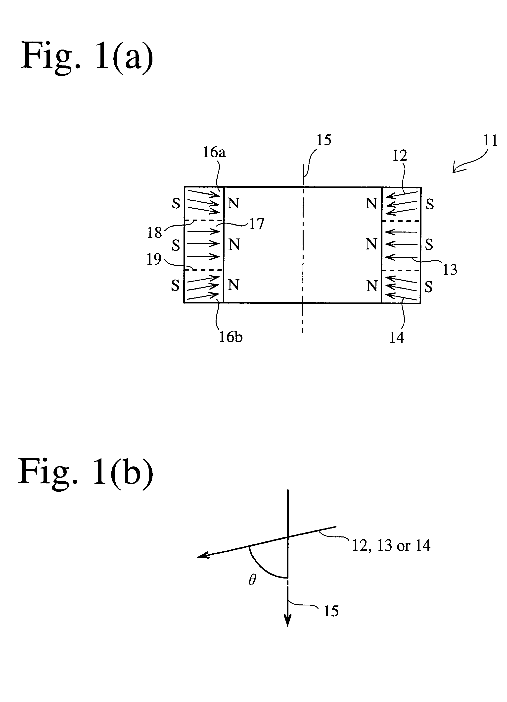
The radially anisotropic ring magnet according to one embodiment of the present invention comprises at least one first radially anisotropic region having a radial anisotropy direction of 89.degree. or more relative to a center axis thereof; and at least one second radially anisotropic region having a radial anisotropy direction of 40.degree. or more and less than 89.degree. relative to a center axis thereof, the first and second radially anisotropic regions being arranged along the center axis such that a space magnetic flux density distribution on an inner or outer surface of the ring magnet has increased linearity and / or peak value.
The radially anisotropic ring magnet according to another embodiment of the present invention comprises a plurality of radially anisotropic regions having radial anisotropy directions of 40.degree. or more and less than 89.degree. relative to a center axis thereof, the plurality of radially anisotropic regions being arranged along the center axis such that a space magnetic flux density distribution on an inner or outer surface of the ring magnet has increased linearity and / or peak value.
To improve magnetic properties, at least one of Nb, Al, Co, Ga and Cu is preferably added in a proper amount.
The content of Nb is preferably 0.1-2% by weight. The addition of Nb results in the formation of borides of Nb during the sintering process, thereby suppressing the irregular growth of crystal grains. When Nb is less than 0.1% by weight, enough effects are not obtained. On the other hand, when Nb is more than 2% by weight, too much Nb borides are formed, resulting in drastic decrease in Br.

Problems solved by technology

Therefore, it is actually difficult to increase the thrust of the voice coil.

Method used


Image

  • Speaker comprising ring magnet
  • Speaker comprising ring magnet
  • Speaker comprising ring magnet

Examples


example 2

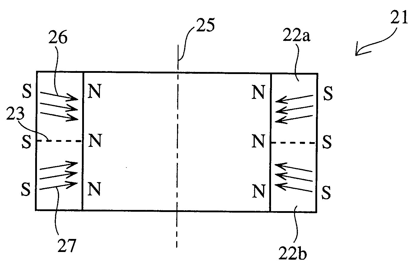
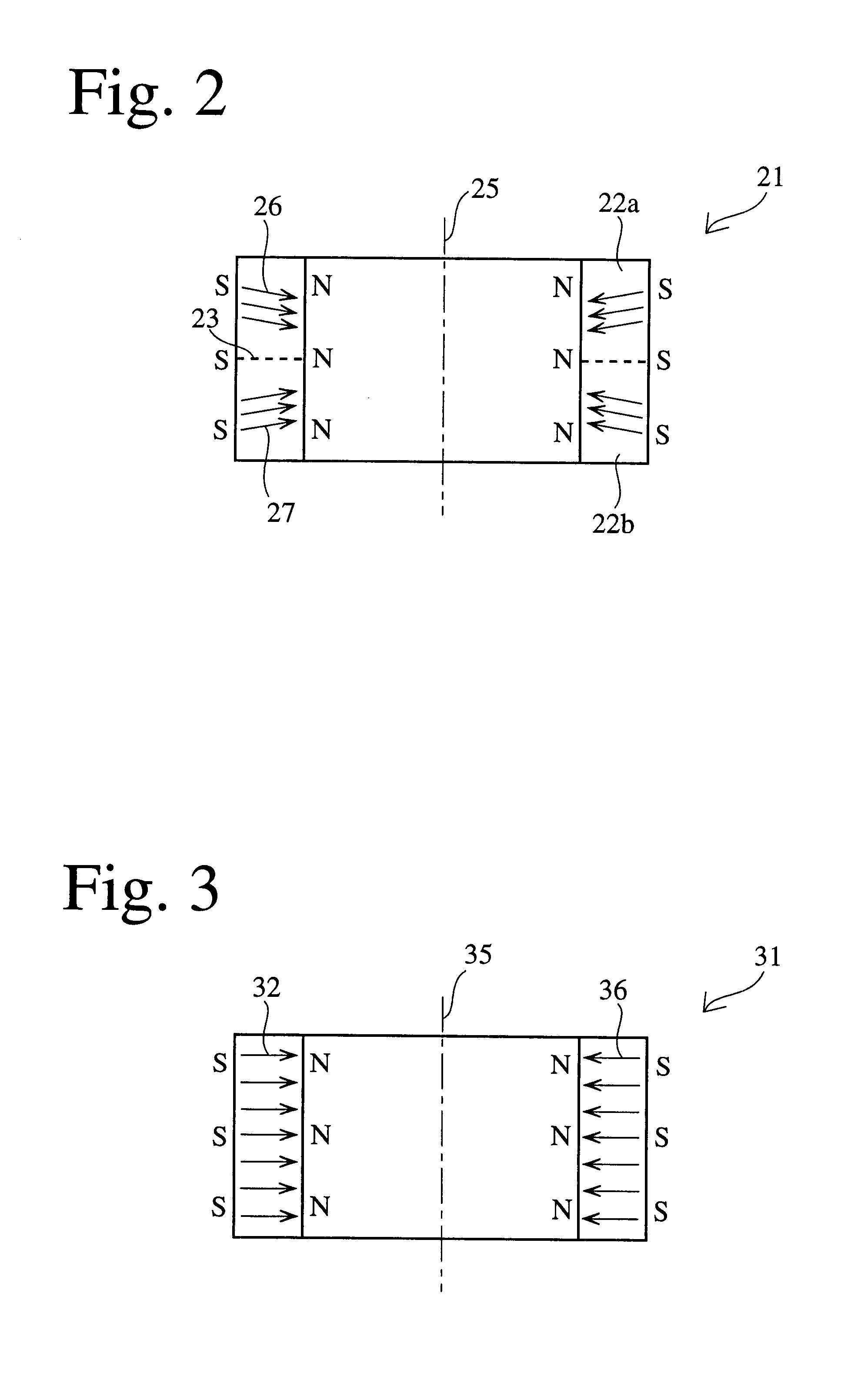
A ring magnet was produced in the same manner as in EXAMPLE 1 except that a magnetic field applied during the compression molding was a radially orienting magnetic field corresponding to FIG. 2, and then evaluated. Its magnetic field analysis revealed that the ring magnet of this EXAMPLE had radially anisotropic regions shown in FIG. 2, as shown in Table 1.

example 3

In a speaker 50 shown in FIG. 4(a), a space magnetic flux density distribution in a magnetic gap 57 was measured when vertically moving from a center O of the magnetic gap 57 as shown in FIG. 4(b). Incidentally, the center O is positioned on an extension of a centerline 60 dividing the ring magnet 11 in a longitudinal direction. The measurement results are shown in FIG. 5.

example 4

A speaker was produced in the same manner as in EXAMPLE 3 except for using the ring magnet formed in EXAMPLE 2, and a space magnetic flux density distribution of the magnetic gap of this speaker in a vertical direction from the center thereof was measured. The results are shown in FIG. 5.


PUM

PropertyMeasurementUnit
diameteraaaaaaaaaa
temperatureaaaaaaaaaa

Abstract

A ring magnet having improved linearity and / or peak value in a pace magnetic flux density distribution, comprising at least one first radially anisotropic region having a radial anisotropy direction of 89° or more relative to a center axis thereof, and at least one second radially anisotropic region having a radial anisotropy direction of 40° or more and less than 89° relative to a center axis thereof, the first and second radially anisotropic regions being arranged along the center axis such that a space magnetic flux density distribution on an inner or outer surface of the ring magnet has increased linearity and / or peak value.

Description

The present invention relates to a radially anisotropic ring magnet with improved linearity and / or peak value in a space magnetic flux density distribution than those of conventional ring magnets, and a speaker comprising such a radially anisotropic ring magnet for having improved linearity and / or peak value in thrust of a voice coil.Speakers of moving coil type have conventionally been used widely. A moving coil-type speaker is a speaker comprising a magnet and a yoke for generating a thrust for moving a voice coil in a magnetic gap, the voice coil coupled with a vibration system being movably disposed in the magnetic gap, and a driving current is caused to flow through the voice coil to generate sound.FIG. 6 is a cross-sectional view showing an important part of a conventional moving coil-type speaker. In FIG. 6, a frame 1 formed by die-cast aluminum, etc. comprises a substantially conical upper frame 1a and a substantially arm-shaped lower frame 1b coupled with each other by scre...

Claims


Application Information

Patent Timeline
Patent Type & Authority Patents(United States)
IPC IPC(8): H01F41/02H01F7/02H04R9/02H01F1/08H02K15/03H02K33/18H04R13/00
CPCH01F7/0284H04R9/025H01F41/028
Inventor SHIMIZU, MOTOHARUDAICHOH, HIROYUKI
Owner HITACHI METALS LTD
Learn More