Top drive casing system

a casing system and top drive technology, applied in the direction of sealing/packing, drilling pipes, borehole/well accessories, etc., can solve the problems of torque head failure, torque head failure, and personnel injury,

Inactive Publication Date: 2003-03-25
WEATHERFORD TECH HLDG LLC
View PDF30 Cites 339 Cited by
  • Summary
  • Abstract
  • Description
  • Claims
  • Application Information

AI Technical Summary

Benefits of technology

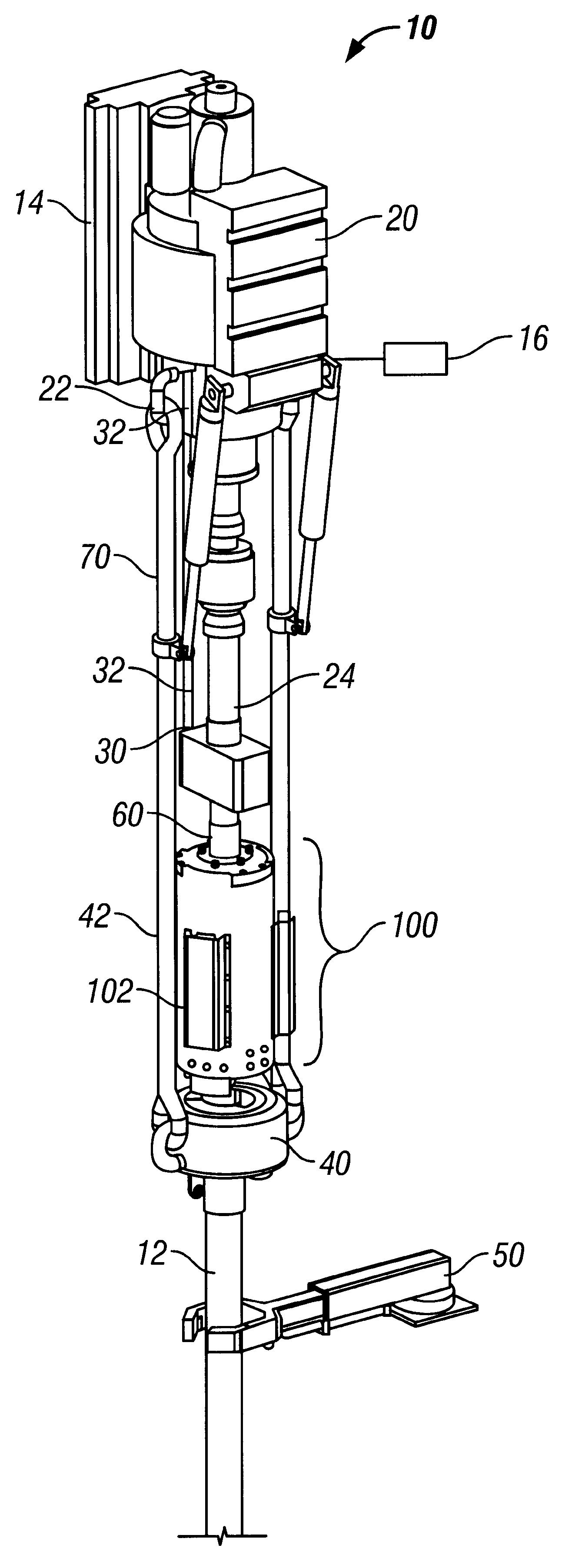
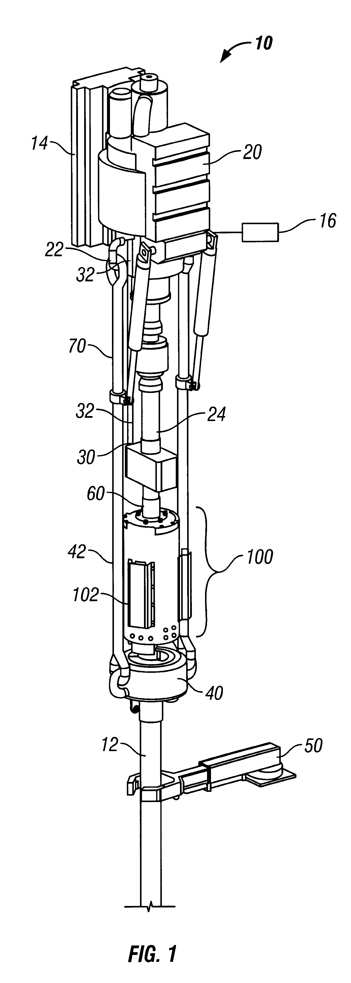
The present invention, in certain aspects, provides a system with a top drive and its related apparatus, and a torque head connected to and below the top drive in a rig for selectively gripping casing. The present invention, in certain embodiments, discloses a torque head useful in such systems and methods, the torque head with jaws with grip members, including but not limited to, slips, dies, and inserts; and in one particular aspect slips with movable dies or inserts that have some degree of axial freedom with respect to the jaws so that, in one aspect, when the slips first contact the exterior of a casing section the dies or inserts move axially with respect to the casing rather than radially, i.e. initially they do not bite, or bite only minimally, into the casing. Then, as the casing is moved by the top drive slips allow limited vertical movement both upward and downward. This allows the slips, dies or inserts to move upward relative to the slips as they engage the casing and to move downward relative to the slips as they are disengaged from the casing.
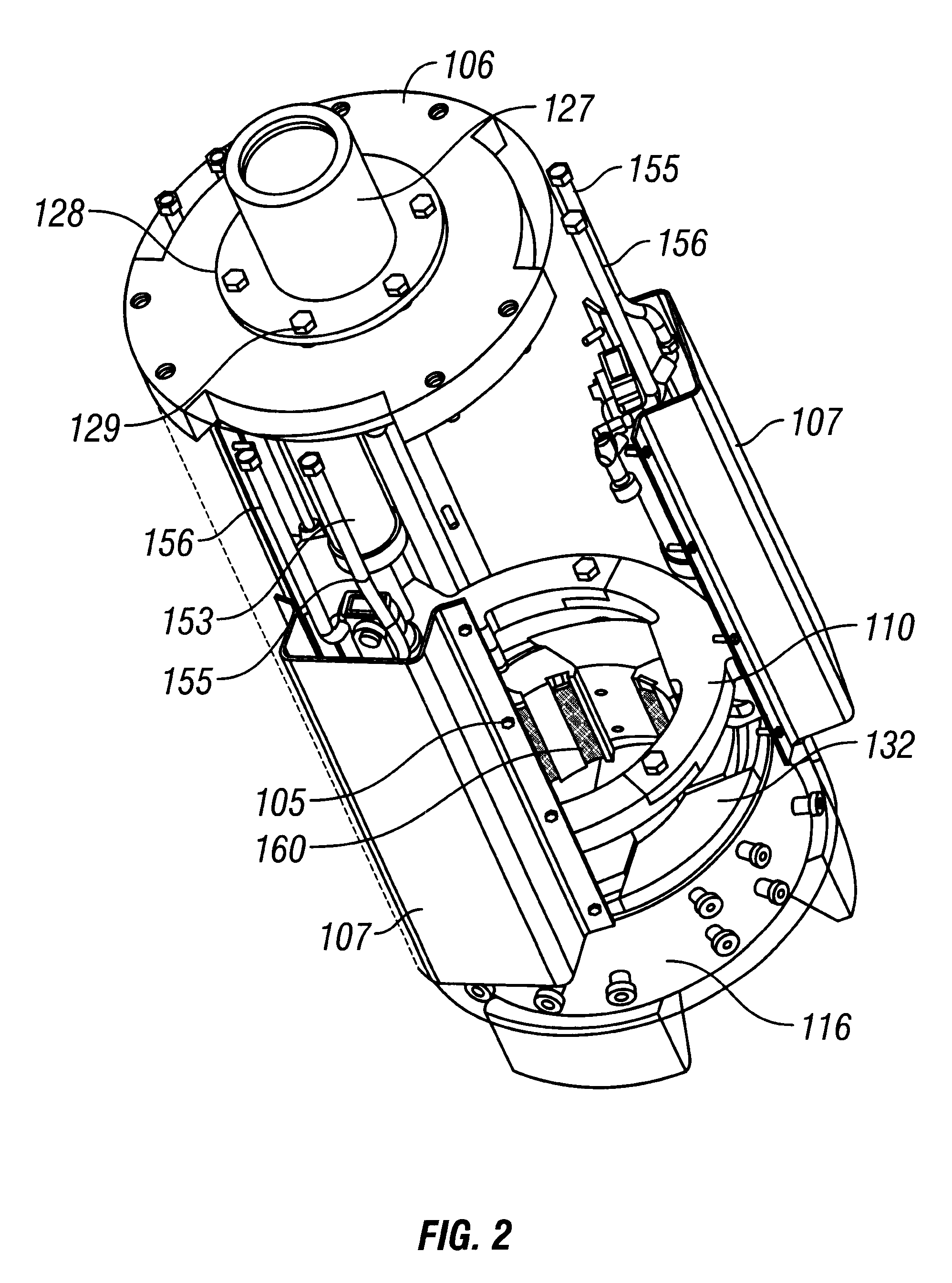
In certain particular embodiments of the present invention relative axial movement of the torque head with respect to a casing joint being gripped by the slips is also made possible by providing a mounting plate assembly that includes bolts holding it together and springs that allow some controlled axial movement of the torque head. With the slips gripping the casing, a torque head barrel is rigidly fixed relative to the casing and if the casing is made up to the string or is gripped at the spider, downward force on the torque head assembly causes the springs located in the top plate to compress and allows for limited axial movement relative to the casing and elevator, provided the elevator slips are engaged on the casing. Such a torque head can be used with the previously-mentioned movable dies, etc., (which engage the casing when they are moved axially downwardly relative to the inner diameter of the torque head) and which are disengaged by axial movement upwardly relative to an inner diameter of the torque head. In the event the torque head assembly is subjected to a dangerous axial load of predetermined amount (e.g., but not limited to, about 100 tons or more), the bolts fail before significant damage is done to the torque head. When the bolts fail, the top plate assembly separates from the torque head barrel while the slips of the torque head assembly remain engaged against the casing, thus causing the barrel and slip mechanism within the barrel to remain firmly attached to the casing and prevent it from free falling the rig floor. This also reduces the possibility of items falling down (e.g. the torque head) and injuring personnel.
Methods according to the present invention with systems according to the present invention are more automated than previous systems because in various prior art systems the torque head can become locked onto the casing when the slips of an elevator (or other suspension / clamping device) are engaged against the casing after the slips of the torque head have been engaged. This condition is a result of the actuation of hydraulic cylinders and then not being able to provide sufficient force to disengage the slips and overcome the mechanical advantage created by the wedging action of slip assemblies without some relative vertical movement of the casing. With the slips of the elevator set, this relative vertical movement of the casing is prevented. The same condition exists for the slips of the elevator in various prior art systems so that the torque head and elevator are locked onto the casing. Various methods are employed to prevent or preclude the torque head from becoming locked onto the casing. In one aspect the dies are capable of some vertical movement relative to the slips. In another aspect in the torque head barrel some limited vertical movement relative to the casing is allowed due to the two piece construction of the torque head barrel top assembly with incorporated spring washers. When the need to use a power tong to makeup a casing string is eliminated, as with systems according to the present invention, the need for a tong running crew is also eliminated.
It is, therefore, an object of at least certain preferred embodiments of the present invention to provide: New, useful, unique, efficient, and novel and nonobvious system and methods for running casing with a top drive;
Such systems and methods which reduce or eliminate damage to casing by using grippers with movable dies or inserts (marking or non-marking); that prevent a torquing apparatus from becoming locked onto casing and / or which reduce or eliminate axial loading on a torquing apparatus and / or by providing for shear release of the torque head from an item, e.g. a top drive connected to it

Problems solved by technology

In the event the torque head assembly is subjected to a dangerous axial load of predetermined amount (e.g., but not limited to, about 100 tons or more), the bolts fail before significant damage is done to the torque head.
This also reduces the possibility of items falling down (e.g. the torque head) and injuring personnel.

Method used


Image

  • Top drive casing system
  • Top drive casing system
  • Top drive casing system

Examples


Embodiment Construction

Referring now to FIG. 1, a system 10 according to the present invention includes a top drive 20, a torque wrench assembly 30 used for back-up, an elevator 40 (which may also be any suitable known suspendable selective clamping apparatus or device), a pipe handler 50, and a torque head 100. The elevator 40 is suspended by bails 42 from eyes 22 of the top drive 20. The torque wrench assembly 30 is suspended by a support 32 from the top drive 20.

A torque sub 60 interconnects a spindle 24 (also called a "a quill") of the top drive 20 and the top of a joint of casing 12 that extends into the torque head 100. Rotation of the spindle 24 by the top drive 20 rotates the torque sub 60 and the casing joint 12. A top portion of the casing 12 (or of a casing coupling if one is used) extends into the torque head 100.

A selectively operable bail movement apparatus 70 (also called a "pipe handler") moves the bails 42 and elevator 40 as desired. The top drive 20 is movably mounted to part 14 of a rig...


PUM


Abstract

A torque head for gripping tubular members, in at least some aspects, has a housing, grip mechanism secured within the housing, the grip mechanism for selectively gripping a tubular member, the grip mechanism including at least one jaw selectively movable toward and away from a portion of a tubular member within the housing, the at least one jaw having mounted thereon slip apparatus for engaging the portion of the tubular member, the slip apparatus including die apparatus movably mounted to the at least one jaw, the die apparatus movable with respect to the at least one jaw so that relative movement of the tubular with respect to the torque head is possible to the extent that the die apparatus is movable.

Description

1. Field of the InventionThe present invention is directed to wellbore operations, top drives, top drive casing systems and operations, torque heads, top drives with torque heads, and methods using them.2. Description of Related ArtThe prior art discloses many systems and methods for running casing. The prior art also discloses a variety of systems using a top drive for running casing. Certain prior art top drive systems include the attachment of a spider (e.g. but not limited to, a flush mounted spider) suspended beneath a top drive from the bails. The bails are then rigidly fastened to a top drive quill so as to cause the flush mounted spider to rotate in unison with any rotation of the quill. Engagement of the flush mounted spider's slips with a casing joint or string causes the casing to rotate in coordinated unison with the spider. FIG. 17 shows a prior art top drive in which the collective assembly beneath a bull gear is able to rotate and is collectively referred to as the "p...

Claims


Application Information

Patent Timeline
Patent Type & Authority Patents(United States)
IPC IPC(8): E21B19/16E21B19/07E21B19/00E21B3/02E21B21/00E21B33/03E21B33/05E21B3/00E21B21/02
CPCE21B19/07E21B19/16E21B33/05E21B21/02E21B19/165
Inventor SNIDER, RANDY GENESHAHIN, DAVIDALLEN, JIMGRAY, KEVINTHOMPSON, GARY
Owner WEATHERFORD TECH HLDG LLC
Why Eureka
Try Eureka