RF transponder identification system and protocol

a transponder identification and radio frequency technology, applied in the direction of burglar alarm mechanical actuation, using reradiation, instruments, etc., can solve the problems of inconvenient system for medium access techniques, inability of transponders to detect the presence of other transponders, and limited processing capacity of remote stations, so as to improve the system performance and increase the probability of collisions

Inactive Publication Date: 2003-03-25
NAT UNIV OF SINGAPORE
View PDF18 Cites 105 Cited by
  • Summary
  • Abstract
  • Description
  • Claims
  • Application Information

AI Technical Summary

Benefits of technology

In another technique described in U.S. Pat. No. 5,523,749 (See FIG. 2 of the accompanying drawings), the transponders are made to send repeated copies of its identification information. Such a system has the merit of simplicity and is aptly suited for simple systems where the number of transponders in an electromagnetic field is controlled. However, in applications where the number of transponders is large or the same identification information is carried by two or more transponders, then the system would not be able to read all the transponders or would take an indefinite amount of time to read all the transponders. This is because the repeated transmission by the transponders increases the probability of collisions by a factor equivalent to the number of repeated transmissions.
In yet another technique described in European Patent Application 0,685,825 (see FIG. 3 of the accompanying drawings), the system incorporates an interruption to the interrogation signal to indicate that the identification information has been successfully read. The transponder has means to sense the interruption and to cease transmission in response to the interruption `gap`. This improves the performance of the system as compared with the system described in U.S. Pat. No. 5,523,749. It should, however, be noted that the technique is inherently flawed in that given a situation where two transponders at differing distances from an interrogator are transmitting their identification information at the same time, it is possible that the interrogator is able to correctly receive the information from one of the two transponders, if the received power from the second transponder is much lower than the received power from the first, such that the contribution of the second transponder is insignificant so as not to cause any interference to the received identification information from the first transponder. The interrogator would continue to interrupt its interrogation signal indicating correct reception. This interruption, being received by both the transponders would cause both transponders to cease transmitting their identification information, resulting in the `loss` of the second transponder. On a less probable but not impossible note, it is common knowledge that environmental noise can also cause occasional glitches in the interrogation signal and if not properly dealt with, this could be mistreated as an interruption indicator.

Problems solved by technology

However, these medium access techniques are not suitable for a system such as RF identification whereby the remote station's processing capability is largely limited to inexpensive transponders having a low-clock rate and low processing power.
Furthermore, the transponders do not have a defined network structure which therefore prohibits the use of `token` passing techniques.
Due to the nature of the radio frequency field, the transponders also do not have the capability to detect the presence of other transponders in a similar way to carrier detection schemes such as in CSMA / CD.

Method used


Image

  • RF transponder identification system and protocol
  • RF transponder identification system and protocol
  • RF transponder identification system and protocol

Examples


Embodiment Construction

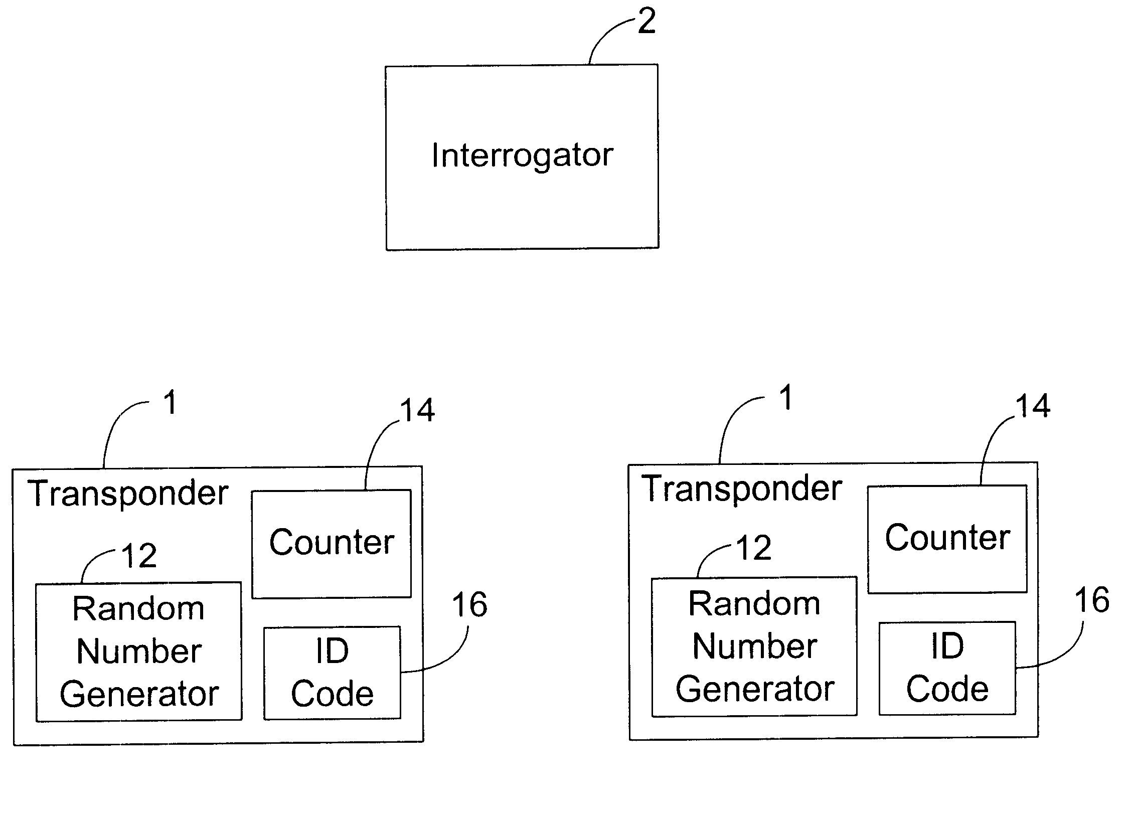
The present invention seeks to provide a protocol or method of identifying or communicating with a plurality of radio frequency (RF) transponders 1 in an electromagnetic field which is controlled by a reader or interrogator 2. The interrogator 2 produces RF signals which are received by all the transponders 1. The transponders 1 are preferably passive components having no power supply of their own and rely upon the received RF signal from the interrogator 2 to power any transmission back to the interrogator 2 so as to identify the transponder 1.

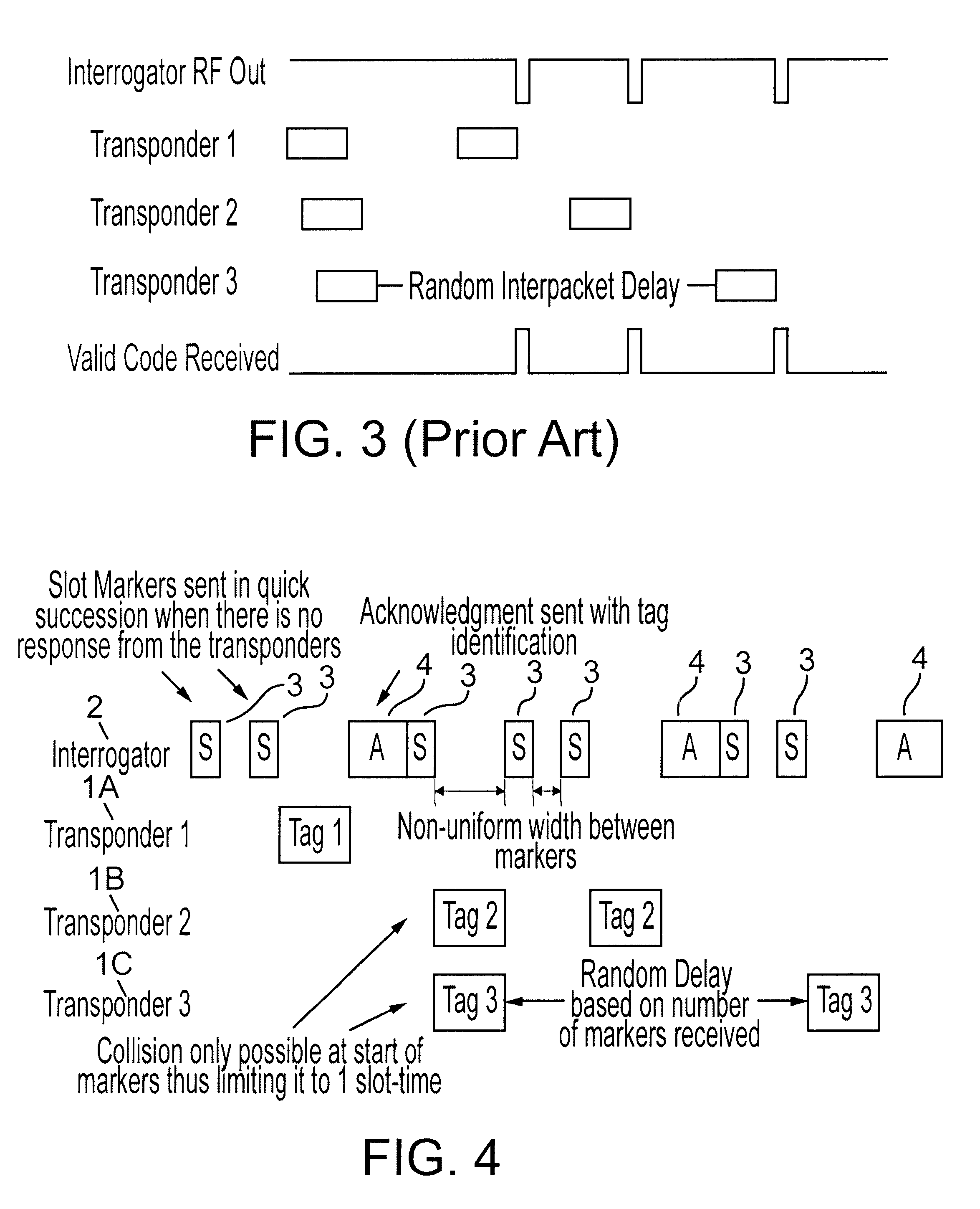
Referring to FIG. 4, the interrogator 2 transmits a plurality of RF signals in time slots of non-uniform duration. These signals are termed slot markers 3 in that the end of the transmission of each slot marker 3 designates a slot within which a transponder 1 can send a signal back to the interrogator 2 to identify the transponder 1.

As illustrated in FIG. 8, each of the transponders 1 includes circuitry to generate a random number 12 and furt...


PUM


Abstract

An RF transponder identification system with an interrogator operable to transmit a plurality of marker signals and a plurality of transponder. Each transponder has a random number associated therewith, a counter counting the number of marker signals received from the interrogator and transmission means to transmit an identification code when the number of marker signals received by the transponder equals the random number associated with the transponder.

Description

THIS INVENTION relates to an RF (radio frequency) transponder identification system and protocol and more particularly to a system and protocol to enable an interrogator to identify a transponder from a group of transponders.Techniques have been devised over the years whereby a number of remote stations share a common channel of communication. From the early days of the simple Aloha technique, to the circuit-switched telephone networks, techniques are evolving and include the present day network medium access control techniques such as token ring (IEEE 802.5), token bus (IEEE 802.4) and Ethernet or CSMA / CD (IEEE 802.3) standards.However, these medium access techniques are not suitable for a system such as RF identification whereby the remote station's processing capability is largely limited to inexpensive transponders having a low-clock rate and low processing power. Furthermore, the transponders do not have a defined network structure which therefore prohibits the use of `token` p...

Claims


Application Information

Patent Timeline
Patent Type & Authority Patents(United States)
IPC IPC(8): G06K7/00
CPCG06K7/10059G06K7/0008
Inventor HENG, KWEE TONG
Owner NAT UNIV OF SINGAPORE
Why Eureka
Try Eureka