Actuation device for a friction clutch in a motor vehicle

a technology of friction clutch and actuation device, which is applied in the direction of mechanical actuation clutches, interlocking clutches, couplings, etc., can solve the problems of insufficient solutions, incongruity between clutch transmission and idle time of release bearing, and the need to replace the clutch facing

Inactive Publication Date: 2003-04-01
ZF FRIEDRICHSHAFEN AG
View PDF7 Cites 15 Cited by
  • Summary
  • Abstract
  • Description
  • Claims
  • Application Information

AI Technical Summary

Benefits of technology

In this connection, the construction of the actuation device according to the present invention makes an extraordinary increase in the life of the release bearing arrangement possible. For operating periods in which the clutch is not to be actuated or in which there is no pending clutch actuation, the actuation device may be adjusted to the non-actuation state in which the release bearing arrangement is decoupled from the release force receiving arrangement with a corresponding gentler treatment of the release bearing arrangement. The actuation device only needs to be moved into the actuation state for clutch actuation and possibly for expected clutch actuation to couple the release bearing arrangement with the release force receiving arrangement. In short, the construction of the actuation device according to the invention allows the release bearing arrangement to run only when it is actually used or when clutch actuation is imminent. Consequently, the release bearing arrangement is exposed to less wear and is therefore more reliable and has a longer life.
Furthermore, the increased reliability and life of the release bearing arrangement which is achieved according to the present invention allows less complicated and therefore economical release bearing components to be used.
In addition to the advantage of increased life and the resulting increased dependability of the release bearing arrangement, the direct transmission of engine vibrations to the release system is eliminated or at least greatly reduced by adjusting the actuation device to the non-actuation state. The pressure medium force cylinder arrangement may, for example, include a pneumatic force cylinder arrangement or a pneumatic ring cylinder. Micromovements of the pressure medium force cylinder induced by engine vibrations contribute to wear of the seals acting between the pressure medium piston and cylinder. Accordingly, an increased life of the seals and accordingly a prolonging of the maintenance-free operating period of the pressure medium force cylinder arrangement is achieved by reducing or eliminating micromovements of the pressure medium force cylinder arrangement deriving from microvibrations.
According to a further embodiment of the present invention, the actuation device may be adjusted to an actuation-ready state in which the release bearing arrangement is coupled with the release force receiving arrangement in the engaged position of the clutch or is proximate the release force receiving arrangement in the engaged position of the clutch so that the release bearing arrangement may be coupled with the release force receiving arrangement with a slight adjustment. According to this further embodiment, the actuation device may be adjusted to the actuation-ready state when a clutch actuation is pending or at least prognosticated. The time constant ascribed to the actuation device for clutch actuation proceeding from the actuation-ready state is substantially smaller than the time constant attributed to a clutch actuation proceeding from the non-actuation state. In this further development, short response times are achieved as is required, for example, for split shifting operations in split-range transmissions.
The control / regulating unit may optionally comprise a prognostic unit which forecasts the frequency and / or probability of future clutch actuations (clutch release processes) in a preview time interval based on operating and / or driving states of the vehicle, operating and / or actuation states of the transmission, operating states of the drive unit, and / or actions of a driver. The control / regulating unit optionally adjusts the actuation device between the non-actuation state and the actuation-ready state depending on the prognosis. The prognostic unit forecasts the frequency and / or probability of future clutch actuations in a preview time interval and accordingly allows the adjustment of the actuation device in response to (1) the instantaneous requirements for switching between the above-mentioned states and (2) the future needs to switch between the states. As was already indicated above, a reduction in the effective time constant of the actuation device with respect to carrying out clutch actuations may be achieved in this way. Moreover, this embodiment avoids the need to constantly adjust the actuation device between the above-mentioned states successively in short time intervals with resulting frequent acceleration of the release bearing arrangement from a standstill, at least under normal driving and operating conditions forming the basis of the prognosis. With respect to acceleration processes, wear on the release bearing deriving from acceleration of the release bearing from a standstill to clutch speed and / or noises deriving from these acceleration processes is appreciably reduced by use of the prognostic unit.

Problems solved by technology

Until recently, clutch facings typically had to be replaced at least once during the life of the engine because of comparatively high facing wear.
However, these solutions still did not produce adequate results.
In Class 8 vehicles in the USA, there is an even greater incongruity between clutch transmission and idle time of the release bearing because shifting occurs without clutch actuation in this class of vehicle.
Micromovements of the pressure medium force cylinder induced by engine vibrations contribute to wear of the seals acting between the pressure medium piston and cylinder.
However, providing a non-actuation state to which the actuation device may be adjusted requires changing the typical actuation device which may forfeit some advantages of the known actuation device.
In this way, the actuation device may acheive very short effective actuation times which even satisfy the very high requirements of split shifting in this respect.

Method used


Image

  • Actuation device for a friction clutch in a motor vehicle
  • Actuation device for a friction clutch in a motor vehicle
  • Actuation device for a friction clutch in a motor vehicle

Examples


Embodiment Construction

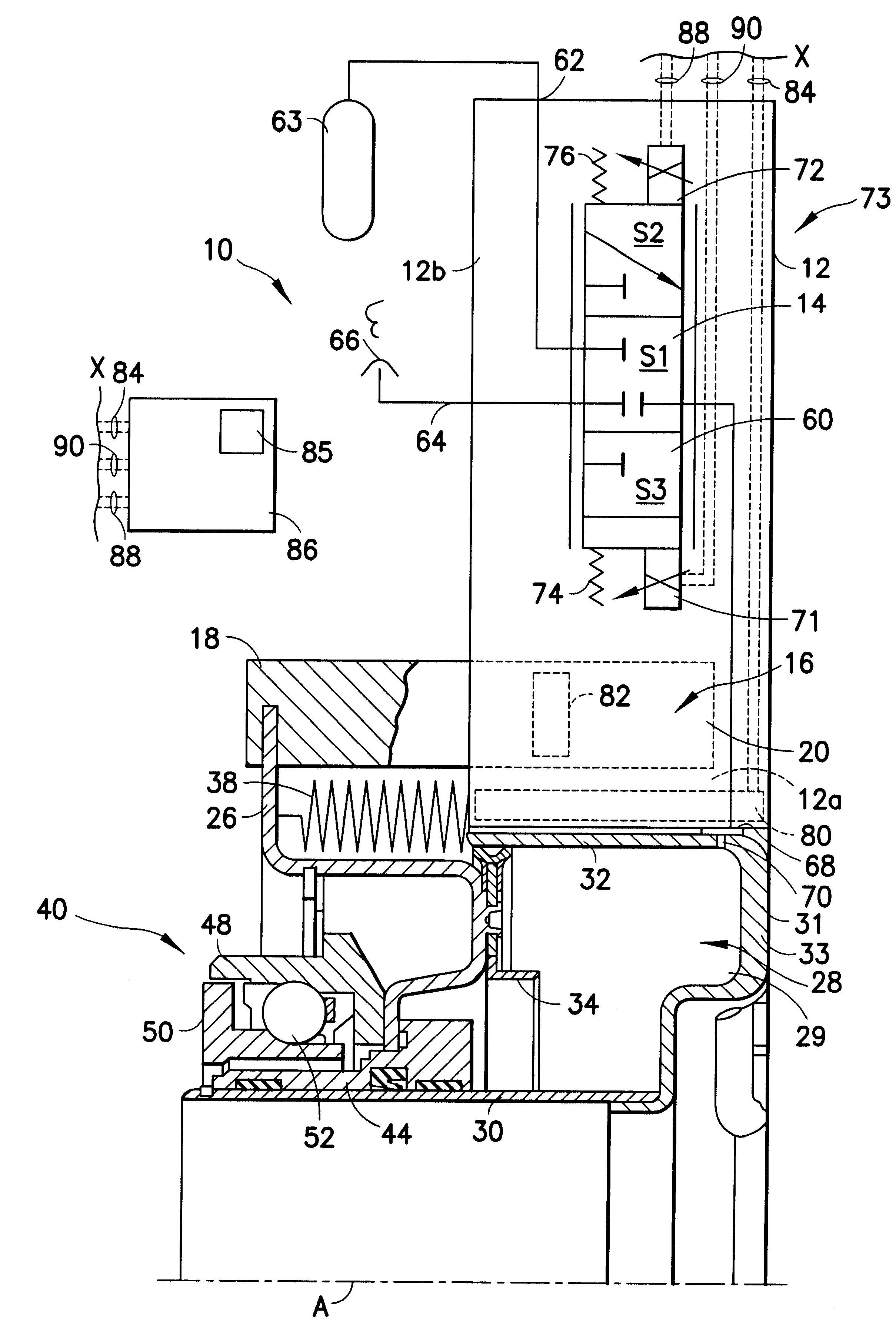
FIG. 1 shows an actuation device 10 (which may also be referred to as a release arrangement 10) according to an embodiment of the present invention. The actuation device 10 is used, for example, in commercial or utility vehicles and is constructed such that it surrounds an axis of rotation A of a motor vehicle friction clutch, not shown in FIG. 1, essentially concentrically. Various components of the actuation device 10 are constructed in a ring-shaped manner and surround the axis of rotation A.

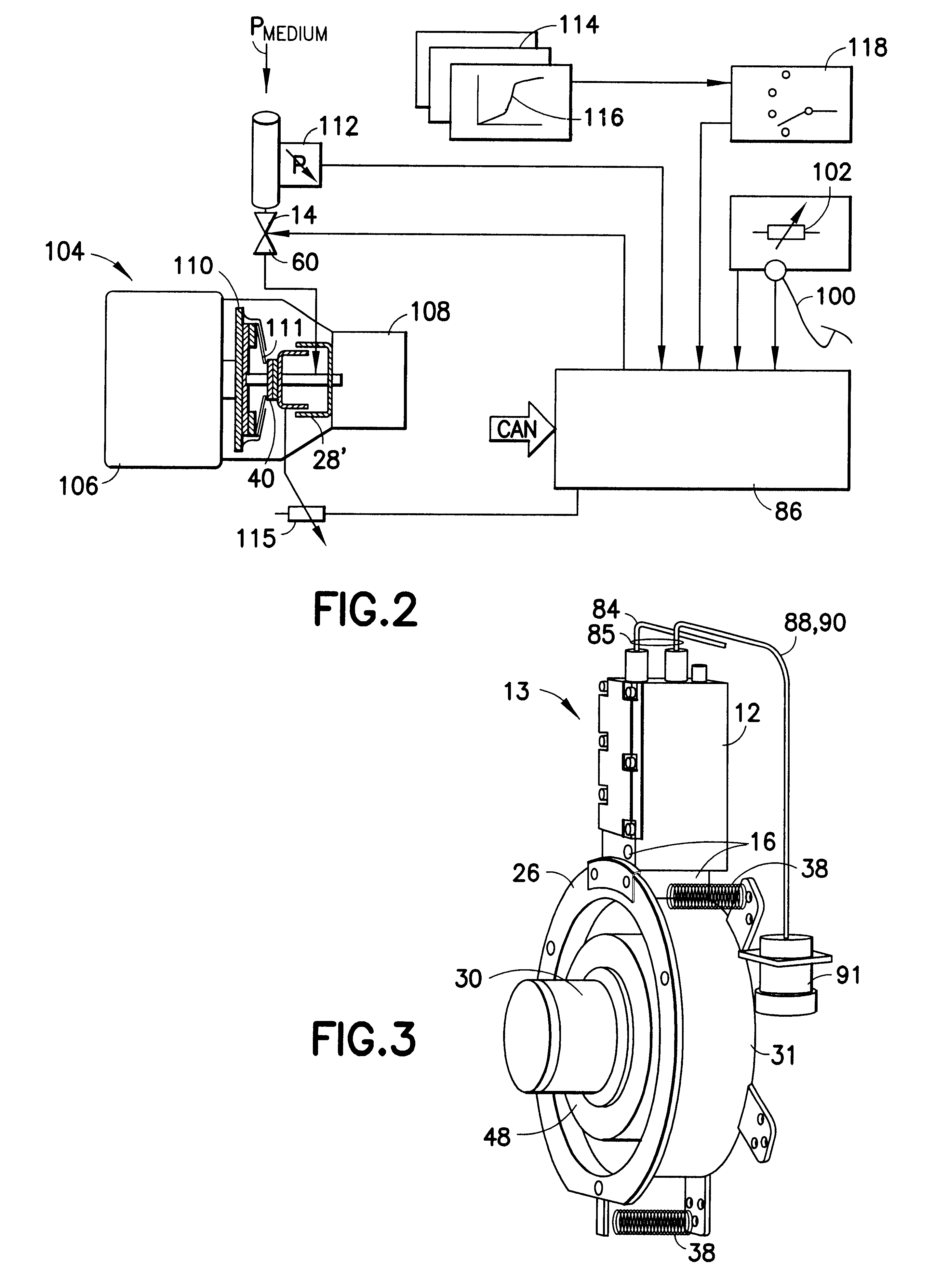
The actuation device 10 includes an actuation unit 13 with a housing 12. A valve arrangement 14, described in further detail below, is integrated in the housing 12 and is shown on the radial outer side 12b thereof. A measuring arrangement 16 is arranged on the radial inner side 12a of the housing 12 and includes a measuring member 18 displaceable along the axis of rotation A. The measuring member 18 is displaceable in a chamber 20 constructed in the housing 12 and open on one axial side.

An en...


PUM


Abstract

An actuation device for a friction clutch which is arranged in the drivetrain of a motor vehicle between a drive unit and a transmission arrangement includes a pressure medium force cylinder arrangement for actuating the friction clutch via a release member having a release bearing arrangement. A measuring arrangement detects an actual release state, i.e., an instantaneous position of the release member. A control / regulating valve arrangement is connected with a pressure medium source, a pressure compensation opening, and with the pressure medium force cylinder arrangement. The pressure medium force cylinder arrangement is actuated depending on the actual release state and on a desired release state. The actuation device is adjustable in a defined manner between a non-actuation state and an actuation state, wherein the release bearing arrangement is decoupled from an associated release force receiving arrangement of the friction clutch in the non-actuation state and is coupled with the release force receiving arrangement in the actuation state.

Description

1. Field of the InventionThe present invention relates to an actuation device for a friction clutch arranged in the drivetrain of a motor vehicle between a drive unit and a transmission arrangement, the actuation device having a pressure medium force cylinder arrangement for actuating the friction clutch via a release member having a release bearing arrangement, a measuring arrangement for detecting an actual release and / or instantaneous release member position, and a control / regulating valve arrangement connected with a pressure medium source, a pressure compensation opening or a pressure compensation reservoir and the pressure medium force cylinder arrangement, the control / regulating valve arrangement arranged for actuating the pressure medium force cylinder arrangement in response to the actual release or the instantaneous release member position and on a reference release which may be predetermined.2. Description of the Related ArtAn actuation device for a friction clutch includ...

Claims


Application Information

Patent Timeline
Patent Type & Authority Patents(United States)
IPC IPC(8): F16D25/08F16D48/00F16D48/02
CPCF16D25/083F16D48/02F16D25/14F16D2300/18F16D48/066F16D2500/1045F16D2500/3024F16D2500/3026F16D2500/31413F16D2500/31493F16D2500/3166F16D2500/702F16D2500/70404F16D2500/7041
Inventor DREXL, HANS-JURGEN
Owner ZF FRIEDRICHSHAFEN AG
Why Eureka
Try Eureka