Polymer-polymer bilayer actuator

a technology of polymer and actuator, applied in the field of actuators, can solve the problems of limited applicability of ceramic actuators, large displacement/strain, heavy and brittle ceramic actuators,

Inactive Publication Date: 2003-04-08
NASA
View PDF27 Cites 54 Cited by
  • Summary
  • Abstract
  • Description
  • Claims
  • Application Information

AI Technical Summary

Problems solved by technology

All of these actuators are found wanting, and, as a result their applicability is limited.
For example, the ceramic actuators are generally heavy and brittle and they provide a small displacement / strain.
Polymer actuators generally also provide either a small displacement / strain (e.g., PVDF), they are subject to environmental limitations (e.g., ionomer), or they have low output force due to low mechanical modulus (e.g., polyurethane, silocone elastomer).
Ceramic-polymer composite actuators also exhibit a small displacement / strain, and they are generally heavy and brittle.

Method used


Image

  • Polymer-polymer bilayer actuator
  • Polymer-polymer bilayer actuator
  • Polymer-polymer bilayer actuator

Examples


Embodiment Construction

should be read with reference to the accompanying Drawings, wherein:

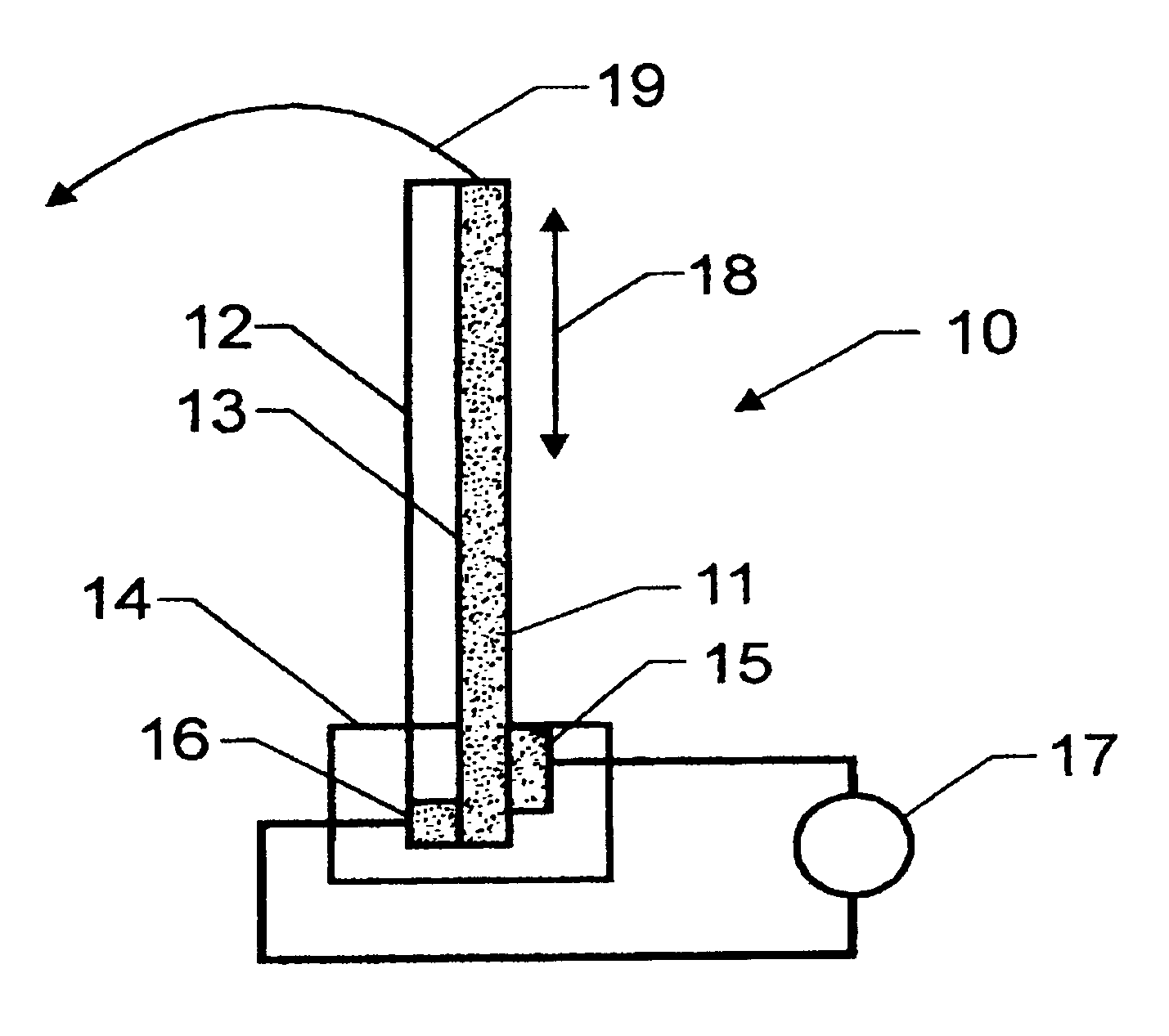
FIG. 1 is a schematic showing the configuration of an embodiment of the present invention under working conditions;

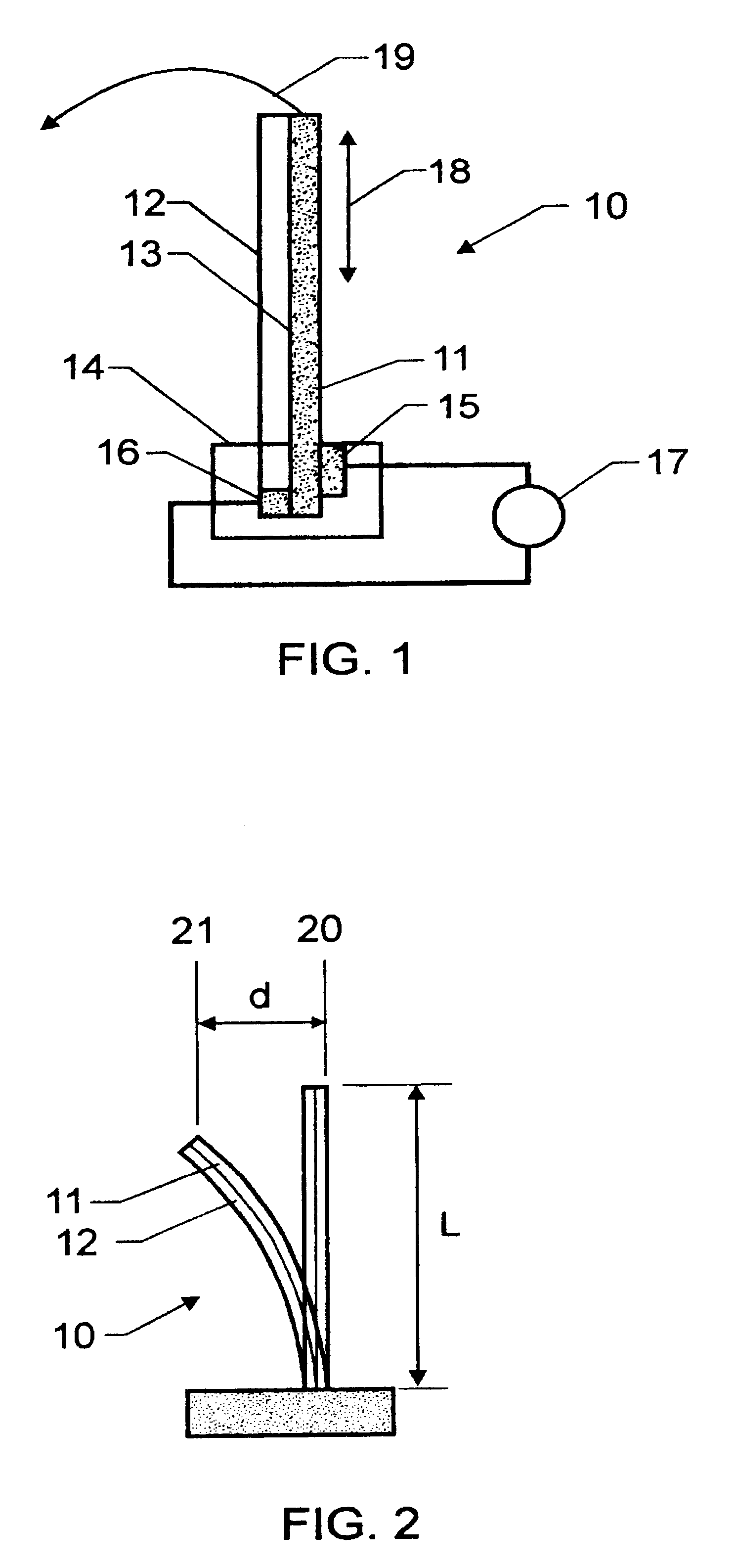
FIG. 2 is a schematic illustrating the quantity tip displacement employing the embodiment of FIG. 1; and

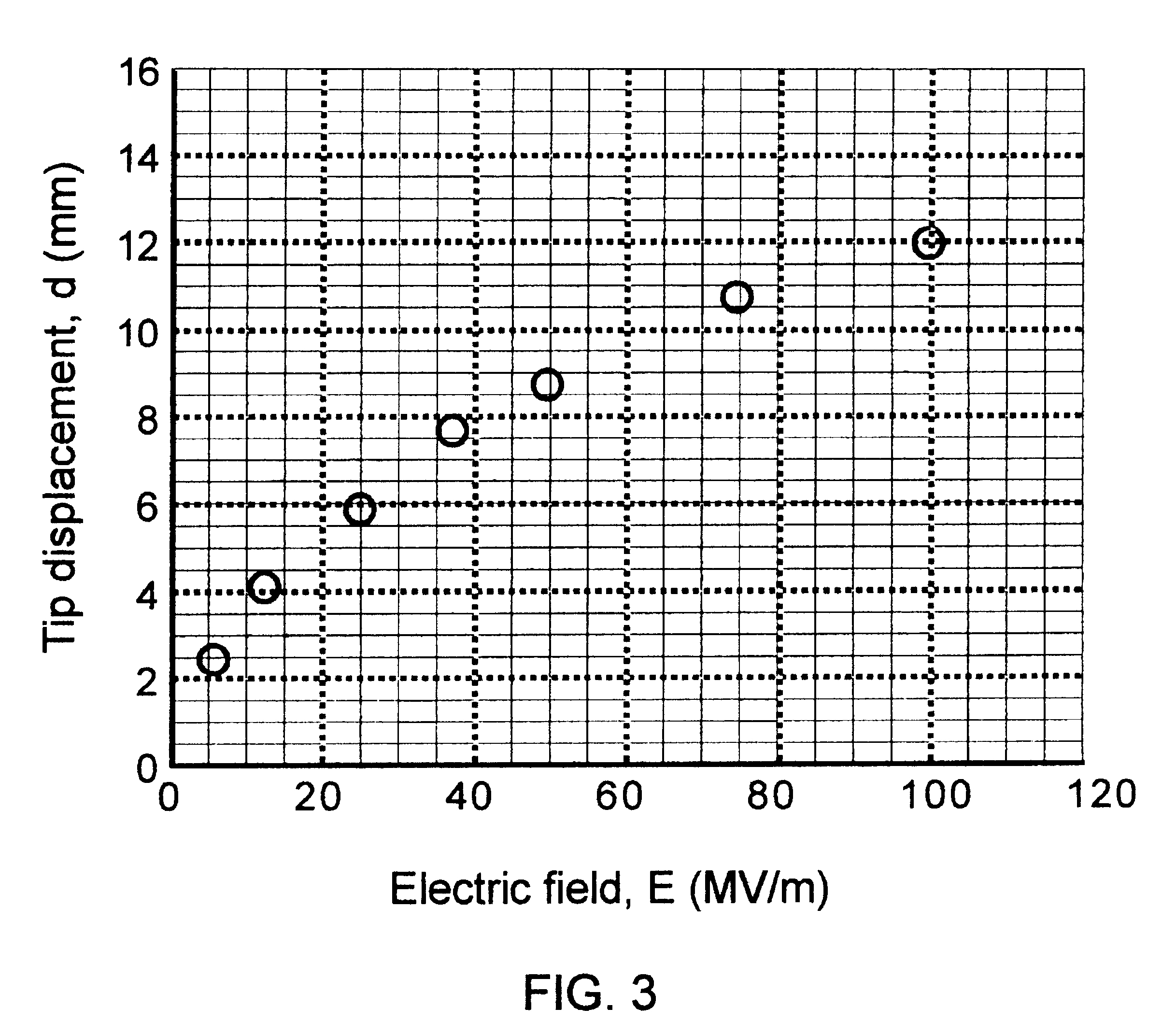
FIG. 3 is a graph depicting the dependence of the tip displacement illustrated in FIG. 2 upon applied electric field.

Referring now to the drawings, FIG. 1 shows as an embodiment of the present invention a device 10 which has 2 elements, viz., an electrically active constituent 11 and an electrically non-active constituent 12, which are bound together along their lengths by bonding means 13, e.g. a chemical bonding means such as a thin layer of an epoxy resin. Mechanical holder 14 holds the device 10 in place, and electrodes 15 and 16 provide contact between opposing surfaces of electrically active constituent 11 and a source of alternating voltage 17. As an example, electrically active constituent 11 ...


PUM


Abstract

A device for providing an electromechanical response includes two polymeric webs bonded to each other along their lengths. At least one polymeric web is activated upon application thereto of an electric field and exhibits electrostriction by rotation of polar graft moieties within the polymeric web. In one embodiment, one of the two polymeric webs in an active web upon application thereto of the electric field, and the other polymeric web is a non-active web upon application thereto of the electric field. In another embodiment, both of the two polymeric webs are capable of being active webs upon application thereto of the electric field. However, these two polymeric webs are alternately activated and non-activated by the electric field.

Description

CROSS REFERENCE TO RELATED CASESThis application is related commonly owned patent application Ser. No. 09 / 696,528, filed Oct. 23, 2000, entitled "Electrostrictive Graft Elastomers."ORIGIN OF THE INVENTIONThis invention was jointly made by employees of the U.S. Government and an employee of the National Research Council and may be manufactured and used by or for the government for governmental purposes without the payment of royalties thereon or therefor.1. Field of the InventionThis invention relates generally to actuators. It relates in particular to a device for providing an electromechanical response which has two polymeric webs bonded to each other along their lengths.2. Description of the Related ArtElectromechanical actuators of the related art include ceramic actuators of various configurations, including those which are direct piezoelectric; polymer actuators, including direct piezoelectric, electrostatic, conductive polymer based, gel based, and ionomeric; and actuators of ...

Claims


Application Information

Patent Timeline
Patent Type & Authority Patents(United States)
IPC IPC(8): F03G7/06H01L41/09H01L41/18H01L41/193
CPCF03G7/06F03G7/065H01L41/094H01L41/193Y10S310/80H10N30/2042H10N30/857F03G7/0613F03G7/0614F03G7/0612
Inventor SU, JIHARRISON, JOYCELYN S.ST. CLAIR, TERRY L.
Owner NASA
Why Eureka
Try Eureka