
Clock recovery and detection of rapid phase transients

a technology of rapid phase transient and clock recovery, which is applied in the field of signal processing, can solve problems such as circuits cannot correct for this apparent malfunction

Inactive Publication Date: 2003-04-15
MICROSEMI FREQUENCY & TIME
View PDF9 Cites 22 Cited by
  • Summary
  • Abstract
  • Description
  • Claims
  • Application Information

AI Technical Summary

Problems solved by technology

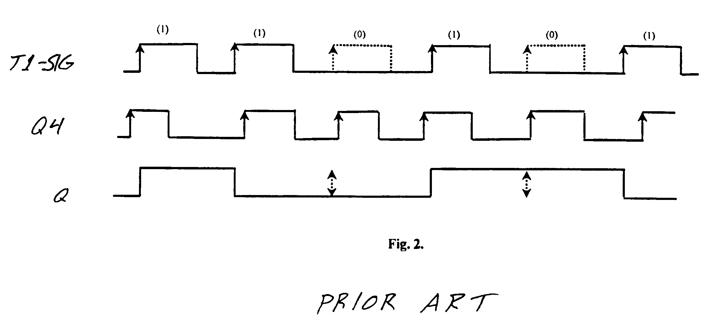
The absence of any pulse in T1-SIG during this period implies that the circuit cannot correct for this apparent malfunction.

Method used


Image

  • Clock recovery and detection of rapid phase transients
  • Clock recovery and detection of rapid phase transients
  • Clock recovery and detection of rapid phase transients

Examples


Embodiment Construction

The invention and the various features and advantageous details thereof are explained more fully with reference to the nonlimiting embodiments that are illustrated in the accompanying drawings and detailed in the following description. Descriptions of well known components and processing techniques are omitted so as not to unnecessarily obscure the invention in detail. It should be understood, however, that the detailed description and the specific examples, while indicating preferred embodiments of the invention, are given by way of illustration only and not by way of limitation. Various substitutions, modifications, additions and / or rearrangements within the spirit and / or scope of the underlying inventive concept will become apparent to those skilled in the art from this detailed description.

The entire contents of U.S. Ser. No. 60 / 173,232, filed Dec. 28, 1999, are hereby incorporated by reference for all purposes as if set forth herein in their entirety.

The clock recovery scheme c...


PUM


Abstract

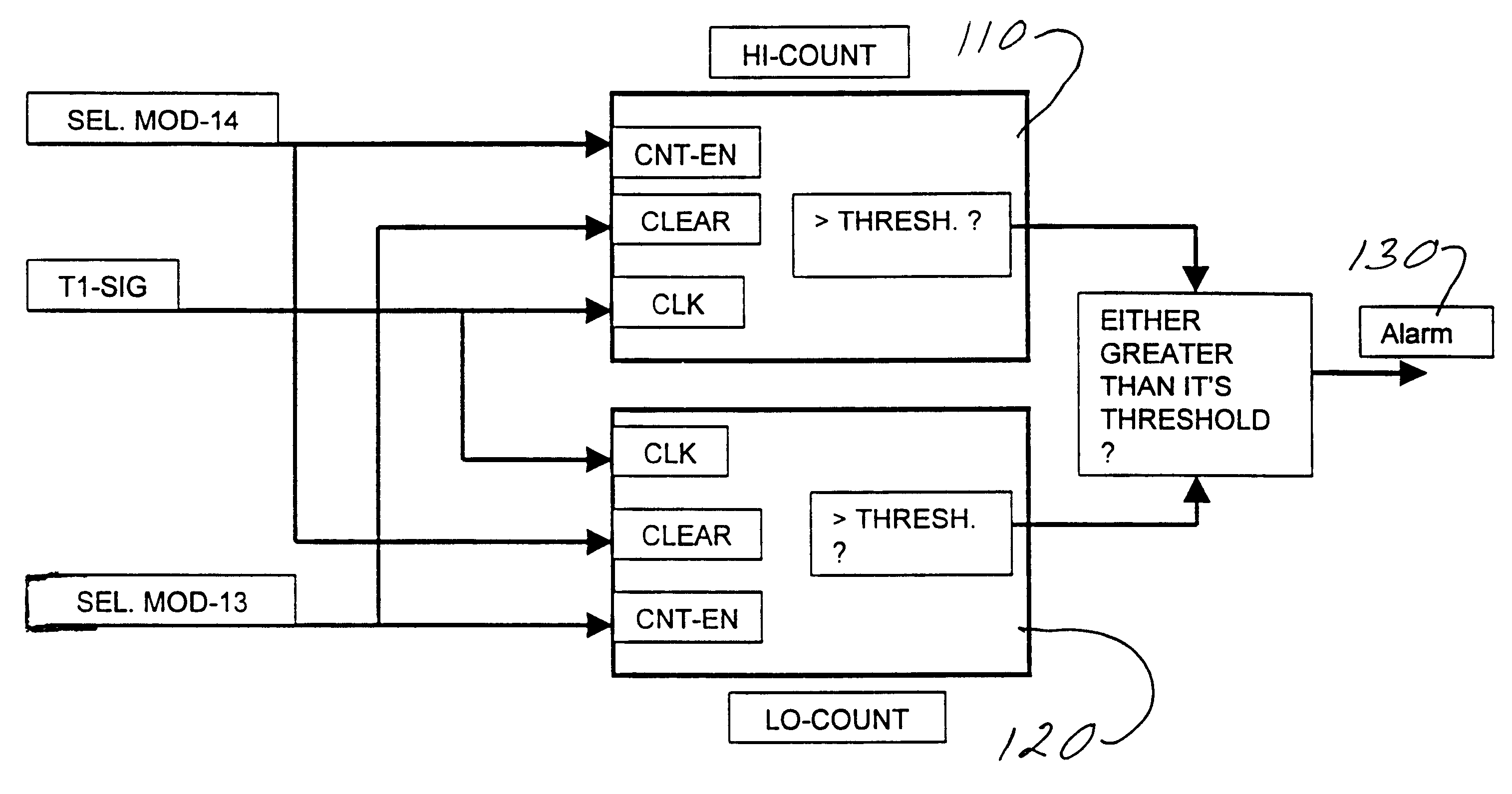
Systems and methods are described for clock recovery and detection of rapid phase transients. An apparatus includes: a numerically controlled oscillator; a phase detector coupled to the numerically controlled oscillator; and a multiplexer coupled to the phase detector and the numerically controlled oscillator, wherein a) the phase detector sets a state variable indicator to either i) a high value if an output phase of the numerically controlled oscillator lags an incoming signal phase, or ii) a low value if the output phase leads the incoming signal phase, b) the multiplexer sends either i) a high increment to the numerically controlled oscillator if the state variable indicator has been set to the high value, or ii) a low increment to the numerically controlled oscillator if the state variable indicator has been set to the low value, and c) the numerically controlled oscillator either i) advances the output phase if the high increment has been sent to the numerically controlled oscillator, or ii) retards the output phase if the low increment has been sent to the numerically controlled oscillator. A method includes incrementing a high counter once every clock cycle if a state variable indicator is high; clearing a low counter if the state variable indicator is high; incrementing the low counter once every clock cycle if the state variable indicator is low; clearing the high counter if the state variable indicator is low; and triggering an alarm signal if either i) the low counter exceeds a low count threshold or ii) the high counter exceeds a high count threshold.

Description

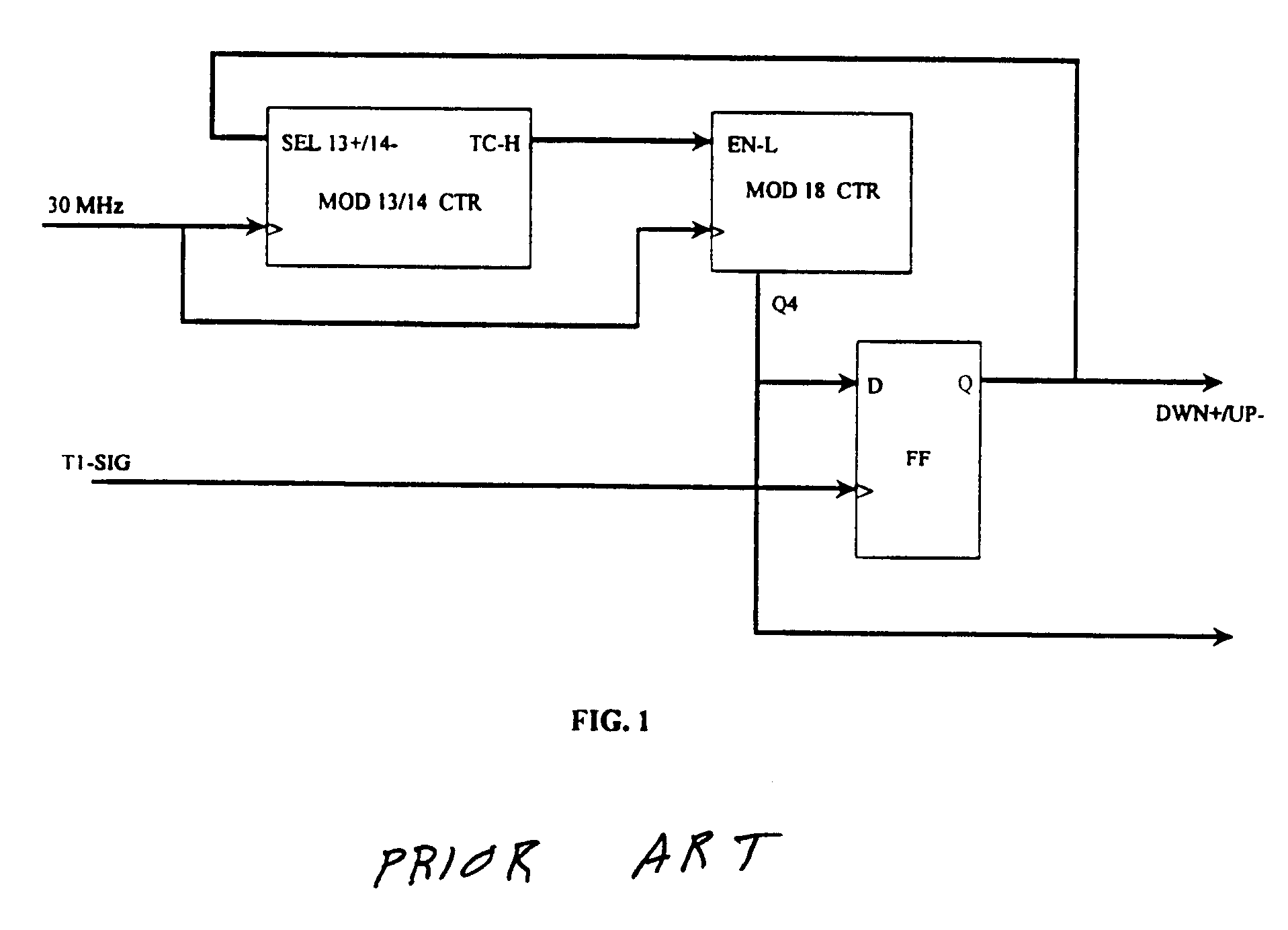
1. Field of the InventionThe invention relates generally to the field of signal processing. More particularly, the invention relates to clock recovery and detection of rapid phase transients.2. Discussion of the Related ArtClock recovery is a fundamental procedure in all digital receivers. For instance, in T1 transmission schemes the serial data is transported as a series of (bipolar) pulses wherein the presence of a pulse indicates a digital "1" and absence of a pulse indicates a digital "0." It is essential that the receiver have an accurate estimate of the duration, separation and position of the pulse (or absence) to decide the nature of the transmitted bit. This, in essence, is the notion of a clock recovery. As one consequence, the receiver makes available a signal that has the same timebase (notion of time interval) as the transmitter.In synchronization equipment, such as the Symmetricom DCD Series, clock recovery is used to establish a reference timebase. An oscillator locke...

Claims


Application Information

Patent Timeline
Patent Type & Authority Patents(United States)
IPC IPC(8): H03L7/099H03L7/089H03L7/08H04L7/033
CPCH03L7/089H03L7/0992H04L7/0331H04L7/033H03L7/0994
Inventor SHENOI, KISHAN
Owner MICROSEMI FREQUENCY & TIME
Learn More