
Method for designing a decoupling circuit

a decoupling circuit and design method technology, applied in the direction of cad circuit design, cross-talk/noise/interference reduction, instruments, etc., can solve the problems of no known design theory by which the circuit designer or user can design the capacitance of the capacitor, and the general emission of unwanted electromagnetic field in digital circuits

Inactive Publication Date: 2003-04-15
NEC CORP
View PDF5 Cites 9 Cited by
  • Summary
  • Abstract
  • Description
  • Claims
  • Application Information

AI Technical Summary

Benefits of technology

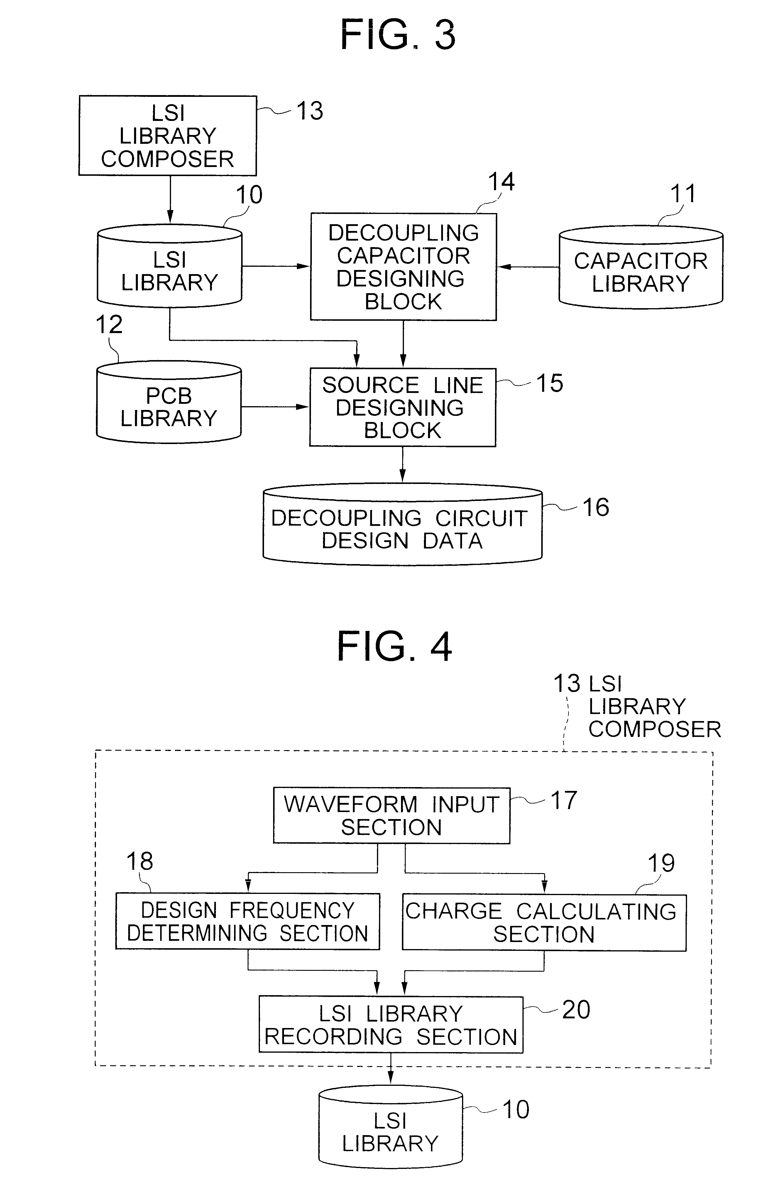
In accordance with the method of the present invention, a decoupling circuit can be designed for the source line of the LSI with a reduced design work. The resultant decoupling circuit has a decoupling circuit which allows the source line and the decoupling capacitor to supply the electric charge necessary for driving the LSI and an inductance of the source line which allows an effective source decoupling for the LSI.

Problems solved by technology

Digital circuits generally generate unwanted electromagnetic field emissions (EMIs) from multilayer printed circuit boards.
The methods described therein, however, have a disadvantage in that the design for selecting the capacitance of the capacitors cannot be specifically determined.
In short, there is no known design theory by which the circuit designers or users specifically determine the decoupling capacitor.
In addition, for a larger number of LSIs disposed on a printed circuit board, it costs a larger amount of time to determine the decoupling capacitors for the respective LSIs.
However, the technique for determining the length of the source line is yet to be established.
The design for layout of the source lines requires a large amount of design work in view of the large number of LSIs mounted on the printed circuit board

Method used


Image

  • Method for designing a decoupling circuit
  • Method for designing a decoupling circuit
  • Method for designing a decoupling circuit

Examples


Embodiment Construction

Now, the present invention is more specifically described with reference to accompanying drawings, wherein similar constituent elements are designated by similar or related reference numerals.

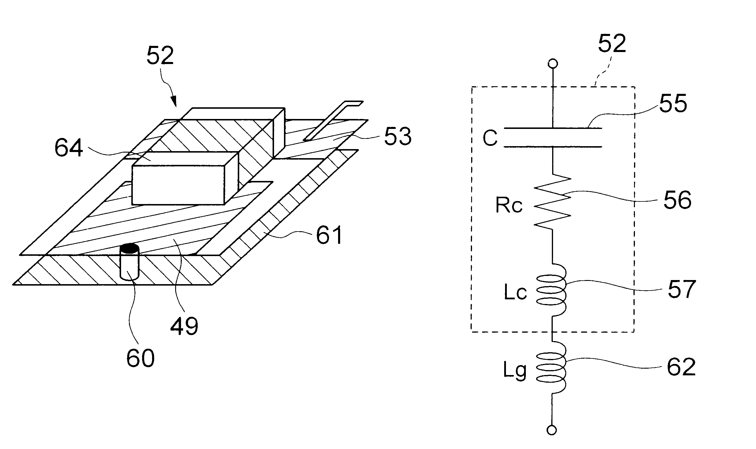
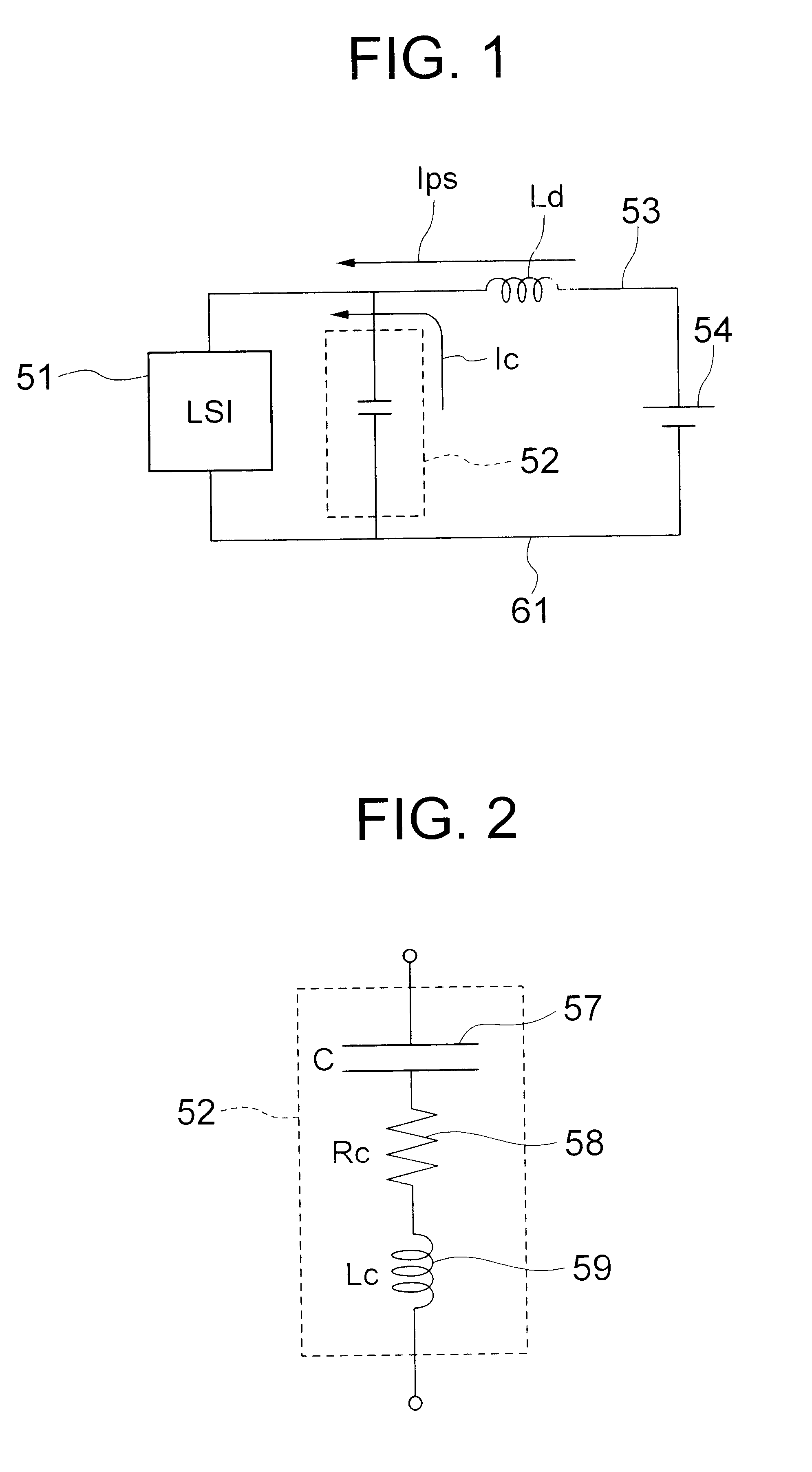
Referring to FIG. 1, a decoupling circuit for a source line to be designed by the method of the present invention includes a decoupling capacitor 52 connected in parallel with an object LSI 51 between a source line 53 and a ground line 61, and a decoupling inductor (Ld) connected in series with the LSI 51 and formed by the structure of the source line 53. The source lines 53 carries current Ips supplied from a power source 54, whereas the decoupling capacitor 52 supplies a current Ic to the LSI during a short interval of the operation thereof. The method of the present invention determines the electric parameters of the decoupling capacitor 52 and the inductor 53.

Referring to FIG. 2, the decoupling capacitor 52 shown in FIG. 1 in fact has a serial electric elements including a capacitance 57, a...


PUM


Abstract

A method for designing a decoupling circuit for a source line of a LSI includes the steps of determining the capacitance of the decoupling capacitor based on the electric charge necessary for one cycle operation of the LSI and the allowable fluctuation of the source voltage, and determining the inductance of the source line based on the impedance of the decoupling capacitor and the allowable minimum multiplexing ratio of the source current by the decoupling capacitor.

Description

(a) Field of the InventionThe present invention relates to a method for designing a decoupling circuit and, more particularly, to a method suitable for designing a decoupling circuit for each of power source lines (power supply lines) of a plurality of semiconductor integrated circuits (LSIs) mounted on a common multilayer printed circuit board.(b) Description of the Related ArtDigital circuits generally generate unwanted electromagnetic field emissions (EMIs) from multilayer printed circuit boards. Most of the EMIs are generated from the signal transmission lines as well as from the power source lines constituting resonators together with the ground layer of the PCB. This fact necessitates employment of a counter measure for the EMIs in the power source line. It is generally effective to use a decoupling circuit for suppressing the EMIs.For instance, in Patent Publications JP-A-10-97560 and JP-A-11-15870, effective areas for disposing capacitors therein for suppressing the EMIs are...

Claims


Application Information

Patent Timeline
Patent Type & Authority Patents(United States)
IPC IPC(8): G06F17/50H05K3/00H05K1/02
CPCG06F17/5068H05K3/0005H05K1/0231H05K2201/10689H05K2201/09263G06F30/39
Inventor ANDO, NORIAKIIRINO, HITOSHIWABUKA, HIROSHITOHYA, HIROKAZU
Owner NEC CORP
Learn More