Adjustable scaffold used with concrete-receiving forms

a technology of adjustable scaffolds and concrete, which is applied in the direction of scaffold accessories, building repairs, applications, etc., can solve the problem of limited adjustmen

Inactive Publication Date: 2003-04-22
BOLINGER DAVID N +1
View PDF7 Cites 37 Cited by
  • Summary
  • Abstract
  • Description
  • Claims
  • Application Information

AI Technical Summary

Benefits of technology

1 an adjustable length vertical-member of ample stiffness while maintaining a weight such that one person may readily move the apparatus from place to place;
The user will place the vertical members vertically against the ICF wall just to one side of a column of studs such that the pivot is directly in front of a column of studs. The user will extend the vertical members so that they reach from the floor or ground to a desired height and then place pins through pairs of vertical members (through cooperating holes provided for that purpose) so as to fix the height of the assembly. The foot of the bottom vertical-member is affixed to the ground or floor and the foot is capable of flexing. The setting of the height of the total vertical-member may be performed prior to placing the total vertical-member against the ICF wall. Both flanges of several vertically distributed P-brackets will be detachably attached to the studs while each P-bracket surrounds the vertical-members. The surrounding is such that the vertical member is held up while allowing for slight vertical movement of the wall of ICFs when the wall is made vertical (by the scheme shortly to be described) and when the concrete slurry is poured into the forms. This firm, but not solid, attachment to a wall of ICFs by the vertical member is an important feature of the present invention. The shorter flange of each P-bracket will be attached to, and aligned with, the column of studs that are directly behind the pivot. It is preferred that the shorter flange of each P-bracket be attached to a stud within four inches of the nearest side of the vertical member. This too is an important feature of the present invention as it causes the force produced in the brace member to react almost directly in line with a stud without producing significant torque. The longer flange of each P-bracket will be attached to studs in the adjacent column (an adjacent stud). This is possible, in spite of different manufacturers using different horizontal spacings between studs, because the longer flange has a series of spaced holes such that at least one set is able to reach any adjacent stud. This is an additional important feature of the present invention.
It is inherent in the present invention that one person may, with ease, erect multiple copies of the present invention and use the present invention to plumb the associated ICF wall. The asymmetrical design of the P-bracket is such that it, and thus the present invention, can be used with every known style of ICF block without needing any additional parts or tools. The inherent stiffness of the vertical-members insure that the wall as a whole will be plumb as a unit. To accommodate a need to adjust a tall wall, an optional bottom vertical-member may be used that is preferably six feet longer than the standard bottom vertical-member.

Problems solved by technology

An inherent problem with the use of ICFs is having a wall of ICFs be vertical both just before concrete is poured into the forms and while concrete is poured into the forms.
With the common kicker formed of overlapping boards that are nailed or clamped together, adjustability is limited.

Method used


Image

  • Adjustable scaffold used with concrete-receiving forms
  • Adjustable scaffold used with concrete-receiving forms
  • Adjustable scaffold used with concrete-receiving forms

Examples


Embodiment Construction

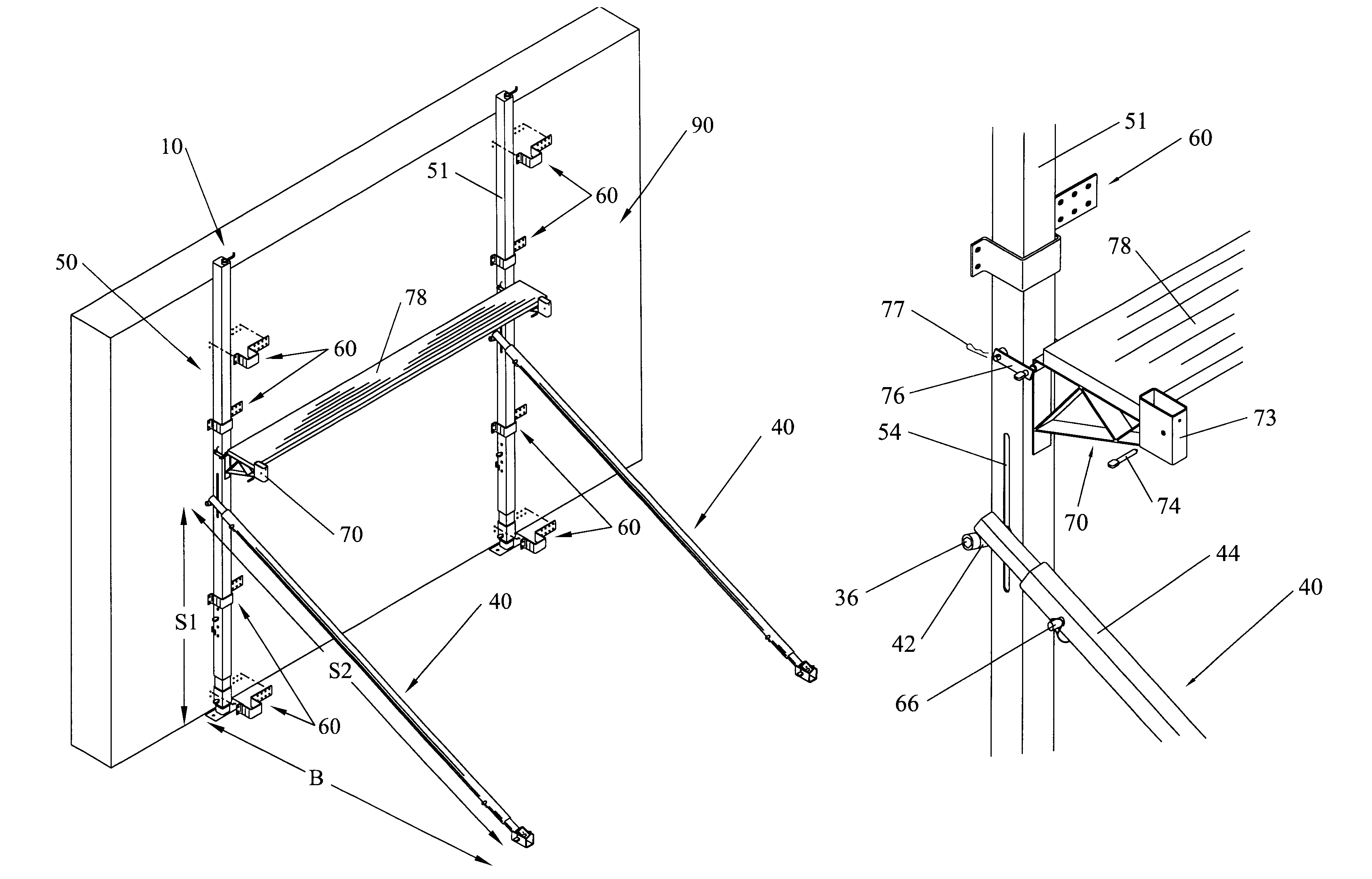
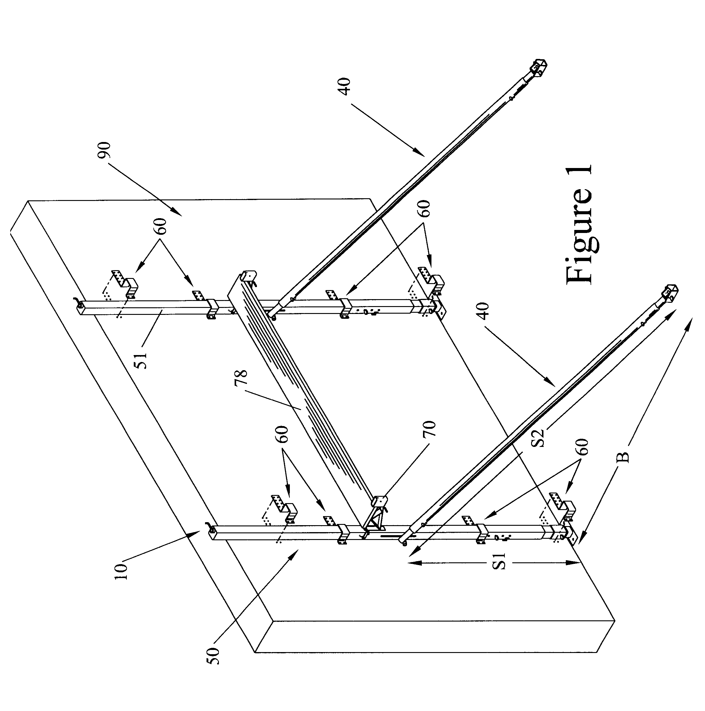
The conformity of the present invention, when in use, is shown on FIG. 1 where two units of the preferred embodiment of the present invention are shown supporting and straightening wall 90. Wall 90 (shown with more detail on FIG. 6) is made up of interlocking expanded polystyrene-construction-blocks 92 that customarily are manually stacked and interlocked so that the block's imbedded studs 94 lie along a series of vertical lines. An example of a suitable interlocking expanded polystyrene-construction-block 92 is described in U.S. Pat. No. 5,428,933.

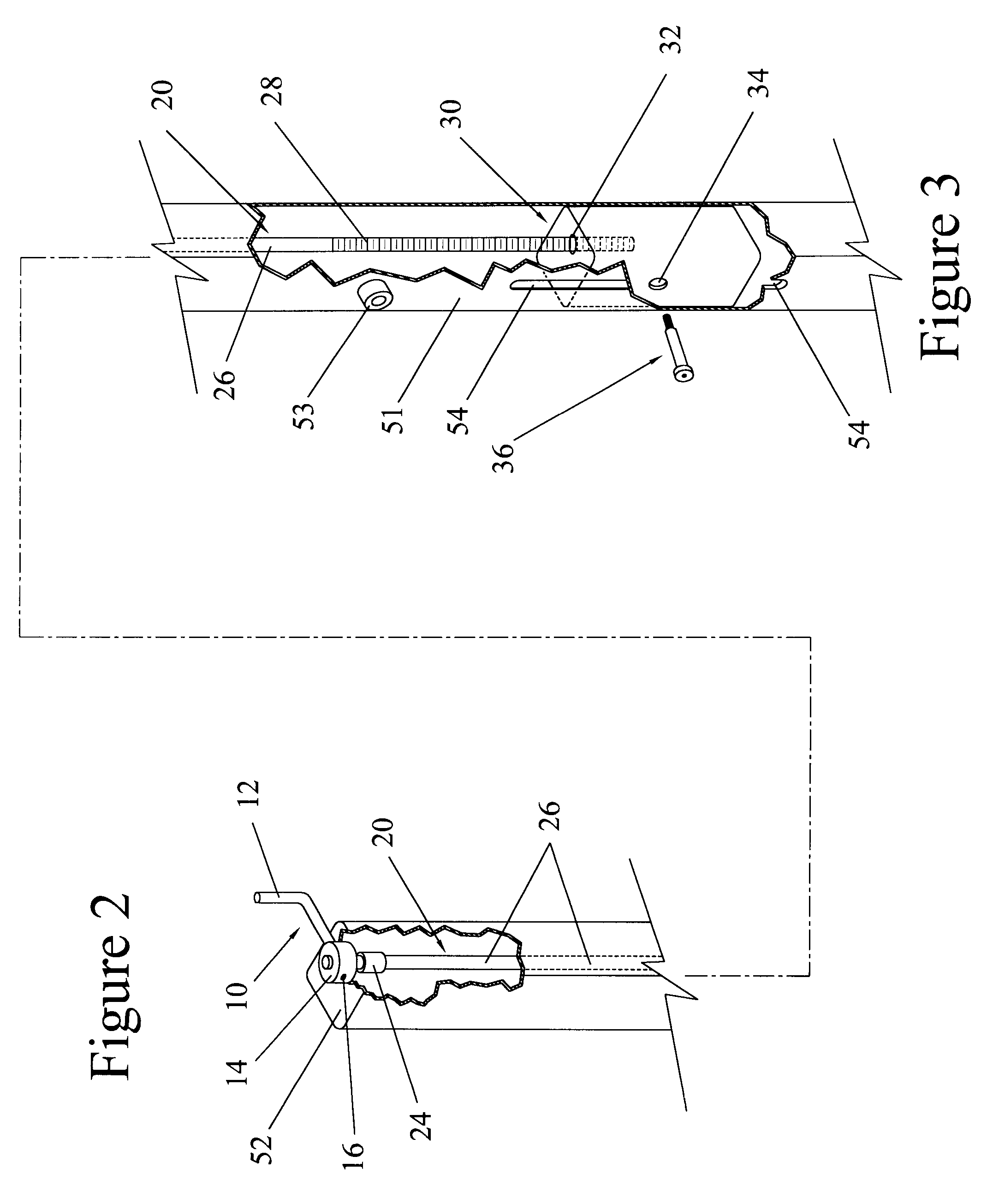
Each unit of the preferred embodiment of the present invention includes crank 10 (to which mechanisms to be described latter are attached) at the top of vertical-member 50 (which is placed essentially vertically against wall 90 and maintained there by P-brackets 60 (which are attached to studs 94)) and brace 40. Platform 78 is held by two or more platform-brackets 70, which extend from, and are supported by, each vertical-member 50.

Longit...


PUM


Abstract

Walls of expanded polystyrene, concrete-receiving forms (referred to as insulated or insulating concrete forms or ICFs) need to be vertical while they are being filled with concrete and while the concrete is curing. An apparatus with a vertical member and a brace member is such that one person can erect it and use it to adjust walls of ICFs so as to be vertical or plumb. The apparatus is capable of being readily used with the forms of any manufacturer by being provided with asymmetrical brackets for detachably attaching the vertical member to a wall firmly, but not rigidly. The apparatus provides a support for a platform, or scaffold, for a person to stand on while guiding the concrete pouring and while plumbing the wall. The vertical member extends upward from the ground and is held firmly against the wall with asymmetrical brackets. The brace member extends from the vertical member at a pivot with the other end of the brace member attached to the ground or floor. A lead screw in the vertical member is used to change the height of the pivot and thus slightly, and adjustably, tilt the vertical member into or out of the wall so as to cause the wall to be vertical. The vertical member and the brace member are preferably adjustable in length, however neither member changes length a noticeable amount while being used to cause the wall to be vertical. The members are preferably made of sections of square cross section, steel tubing that may be nested together.

Description

The field of the invention is that of apparatus:used to cause walls of plastic, concrete-receiving forms to be vertical before and during the pouring of concrete slurry into the forms; andused to provide a platform (scaffold) for a person to stand on safely while guiding the pouring of concrete slurry.The plastic most used for such forms is expanded polystyrene and the plastic shall be so described although other types of plastic might be used.The field of the invention also includes such apparatus that one person can erect and use to adjust walls of expanded polystyrene, concrete-receiving forms so as to be vertical. The field of the invention further includes such apparatus that may readily be used with the expanded polystyrene, concrete-receiving forms of any manufacturer.BACKGROUND INFORMATIONA method of constructing high quality walls has become popular, especially in areas with cold Winters or hot Summers. This method uses a quantity of expanded polystyrene, concrete-receiving...

Claims


Application Information

Patent Timeline
Patent Type & Authority Patents(United States)
IPC IPC(8): E04G21/24E04G21/26E04G5/00E04G3/20E04G3/28E04G5/06
CPCE04G3/20E04G21/26E04G5/06E04G3/28
Inventor BOLINGER, DAVID N.ROSS, EDWARD J.
Owner BOLINGER DAVID N
Why Eureka
Try Eureka