Tool for rotary chip removal, a tool tip and a method for manufacturing a tool tip

a technology of tool tip and rotary chip, which is applied in the direction of turning tools, boring/drilling tools, reaming tools, etc., can solve the problems of high tension of the thread in the known drill bit, inability to optimize the cutting speed, and practical limitations of the techniqu

Inactive Publication Date: 2003-04-22
SECO TOOLS AB
View PDF16 Cites 75 Cited by
  • Summary
  • Abstract
  • Description
  • Claims
  • Application Information

AI Technical Summary

Benefits of technology

The present invention has as one object to provide an embodiment of milling or drilling tools with interchangeable cutting edges, whereby said embodiment eliminates the problems of prior art tools.
Still another object of the present invention is to provide a method for manufacturing a tool tip from injection molded hard metal whereby cracks and porosities are avoided.

Problems solved by technology

However this technique has practical limitations due to strength reasons when it comes to milling and drilling tools that rotate about longitudinal axes, since the cutting edges are subjected to variable cutting speed.
A drawback with the known drill, as for most drills, is that its not optimized for variable cutting speed.
In addition, the thread in the known drill tends to crack at high tension.
Drawbacks with this technique are problems with cracks in the radially external portion or porosities in the radially inner portion.

Method used


Image

  • Tool for rotary chip removal, a tool tip and a method for manufacturing a tool tip
  • Tool for rotary chip removal, a tool tip and a method for manufacturing a tool tip
  • Tool for rotary chip removal, a tool tip and a method for manufacturing a tool tip

Examples


Embodiment Construction

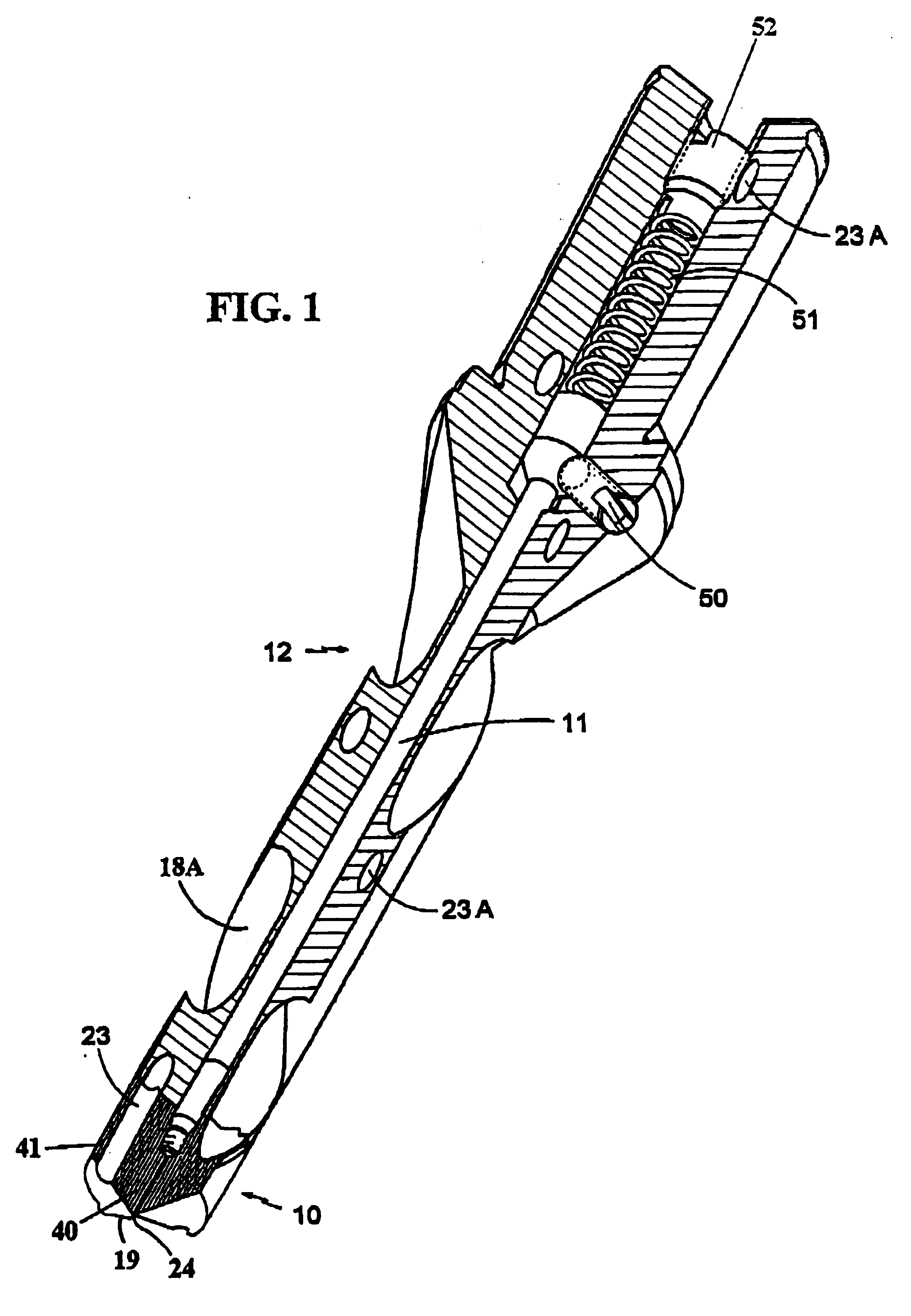
The embodiment in FIG. 1 of a tool according to the invention is a so called helix drill, which in this case includes a tool tip 10, a pull rod 11, a tool body 12, a locking screw 50, a spring 51 and a stop screw 52. With this tool it is possible to untighten and change the tool tip while the tool body is fixed in a machine. The drilling tool has also been described in Karlsson et al. U.S. Pat. No. 5,947,660, the disclosure of which is incorporated herein by reference.

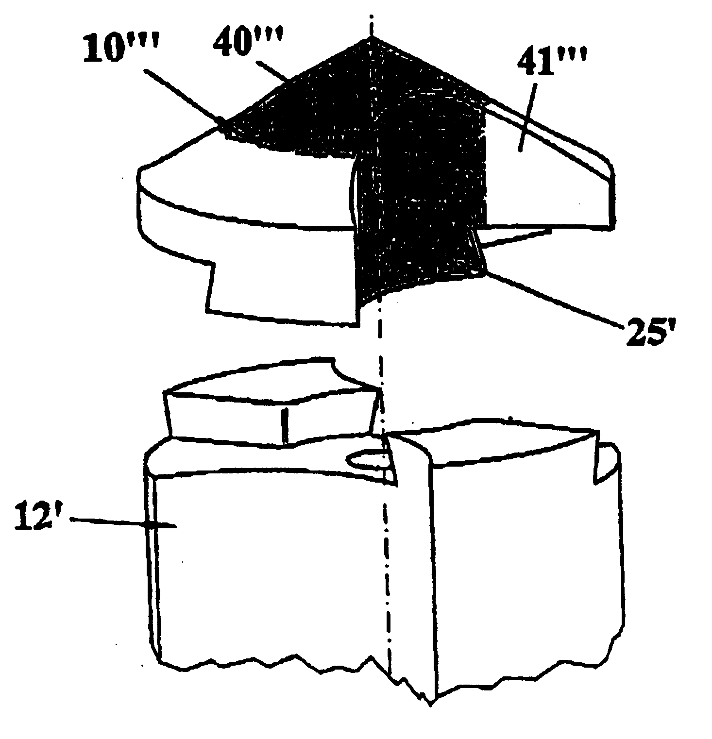
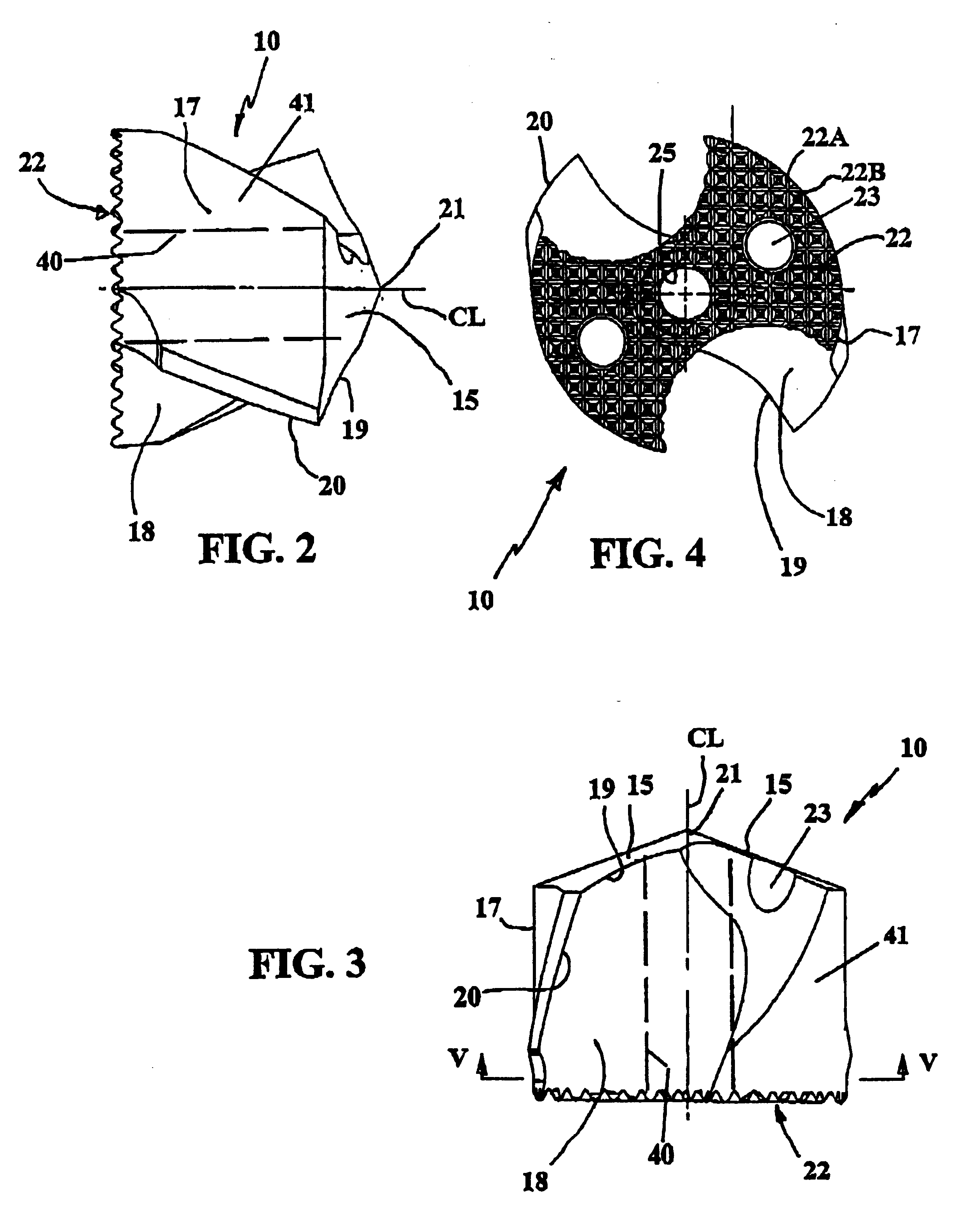
As described in International Publication WO99 / 00208, the tool tip 10 is provided with at least one cutting edge 19 at the front end thereof facing away from the drill body 12, which edge is given a design depending on the area of application. Thus the cutting edge is, or the cutting edges are, substantially straight and parallel to the longitudinal center axis of the cutting portion when the tool tip is an end mill, whereas the cutting edges are circular when the tool tip is a ball nose end mill. The forward end of th...


PUM

PropertyMeasurementUnit
angleaaaaaaaaaa
angleaaaaaaaaaa
radiusaaaaaaaaaa

Abstract

A rotary chip-removing tool includes a rotary tool body and a tool tip fastened on a front end thereof. The tool tip is formed of an injection molded body which has an integral cutting edge at its front end, and a coupling structure at its rear end. The coupling structure can be in the form of a threaded hole, or a rearward projection, for coupling the tool tip against the tool body. The tool tip is formed of first and second materials. The first material forms at least part of the cutting edge, and the second material forms the coupling structure. The first material is more brittle than the second material, and the second material is tougher than the first material.

Description

The present invention relates to a tool for rotary chip removal, comprising a tool body, a tool tip and means for fastening the tool tip to the tool body. The invention also relates to a tool tip per se, and to a method for manufacturing a tool tip.PRIOR ARTIt is previously known to use interchangeable cutting edges on different types of tools for chip removal. However this technique has practical limitations due to strength reasons when it comes to milling and drilling tools that rotate about longitudinal axes, since the cutting edges are subjected to variable cutting speed.Through Karlsson et al. U.S. Pat. No. 5,947,660 there is previously known a drill with an injection molded releasable tool tip anchored in a tool body by means of a pull rod. A drawback with the known drill, as for most drills, is that its not optimized for variable cutting speed. In addition, the thread in the known drill tends to crack at high tension.It is known, through for example, Foster et al. U.S. Pat. N...

Claims


Application Information

Patent Timeline
Patent Type & Authority Patents(United States)
IPC IPC(8): B23B31/10B23B31/11B23B51/02B23B51/00
CPCB23B31/11B23B51/02Y10T408/9098B23B2222/28B23B2222/32B23B2222/84B23B2224/04B23B2224/32B23B2224/36B23B2226/125B23B2226/315B23B2228/10B23B2250/12B23B2251/02B23B2251/14B23B2251/18B23B2251/50Y10S408/713Y10T408/78Y10T408/90993Y10T408/907B23B51/00B23B51/0003B23B51/0004
Inventor BRUHN, JOHNNYPUIDE, MATTIASGRONKVIST, MIKAEL
Owner SECO TOOLS AB
Why Eureka
Try Eureka