
Pressure sensor for measurement of gas pressure in a cylinder of a combustion engine

a technology of pressure sensor and combustion engine, which is applied in the direction of engine testing, structural/machine measurement, instruments, etc., can solve the problems of sensor introducing a dynamic measurement error, negative influence on the working life of the combustion engine, and large variations in the tension in the membrane, so as to reduce the influence, reduce the relative stiffness of the same total wall thickness, and reduce the effect of any differen

Inactive Publication Date: 2003-05-13
ABB (SCHWEIZ) AG
View PDF10 Cites 50 Cited by
  • Summary
  • Abstract
  • Description
  • Claims
  • Application Information

AI Technical Summary

Benefits of technology

In the hourglass embodiment the effects of temperature changes within the cavity have been minimised. Temperature changes, due to short pulses during compression and fuel burning in the cylinder, form a source of error. If the pressure sensor which measures the force due to gas pressure also measures the force due to temperature changes, then the measurement will contain an error. For this reason the walls of the pressure sensor tube 6 have been so formed as to minimise the effects of temperature change. This has been achieved by reducing two of the factors that determine the magnitude of the force due to temperature changes.
A further advantage of the embodiment shown in FIGS. 2, 3, 4 and 5 is conferred by the smooth and uniform internal cross section of the tube-shaped part 6. This discourages the build of any waste or particulate matter from the cylinder gases and allows easy and thorough cleaning. The pressure sensor may be cleaned during a maintenance procedure by, for example, the application of compressed air, or by allowing the combustion gases to pass through the uniform tube with high speed during normal operation of the engine by opening a valve (not shown) situated at the end of the pressure sensor not connected to a cylinder.

Problems solved by technology

Misfiring influences exhaust gas chemical composition and can also negatively influence the working life of a combustion engine.
The disadvantage with that construction is that the membrane and tube have dissimilar temperature coefficients which leads to large variations arising in the tension in the membrane which solely depend on the temperature and which become interpreted as a pressure change.
Even more serious is the fact that the tube is subjected with every pressure pulse to a corresponding adiabatic thermal pulse from compressed gas.
Taken together this means that the pressure sensor introduces a dynamic measuring error which varies with peak pressure and frequency.
The disadvantage with a pressure sensor based on piezo crystals is that they measure only dynamic pressure and consequently cannot be used to measure static pressure.
The changes in diameter in the circular cylinder tube can still not be used for the determination of cylinder pressure on the grounds that there is a column between the measuring membrane and the pressure cylinder and that a extension cannot be transferred via the column.

Method used


Image

  • Pressure sensor for measurement of gas pressure in a cylinder of a combustion engine
  • Pressure sensor for measurement of gas pressure in a cylinder of a combustion engine
  • Pressure sensor for measurement of gas pressure in a cylinder of a combustion engine

Examples


Embodiment Construction

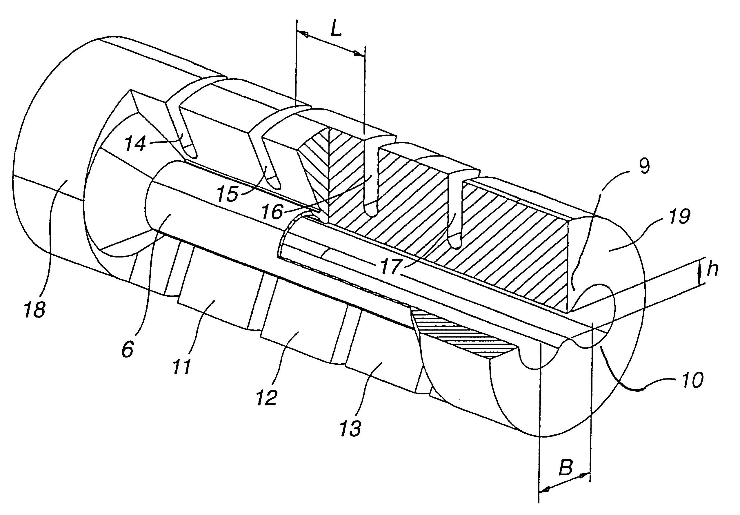
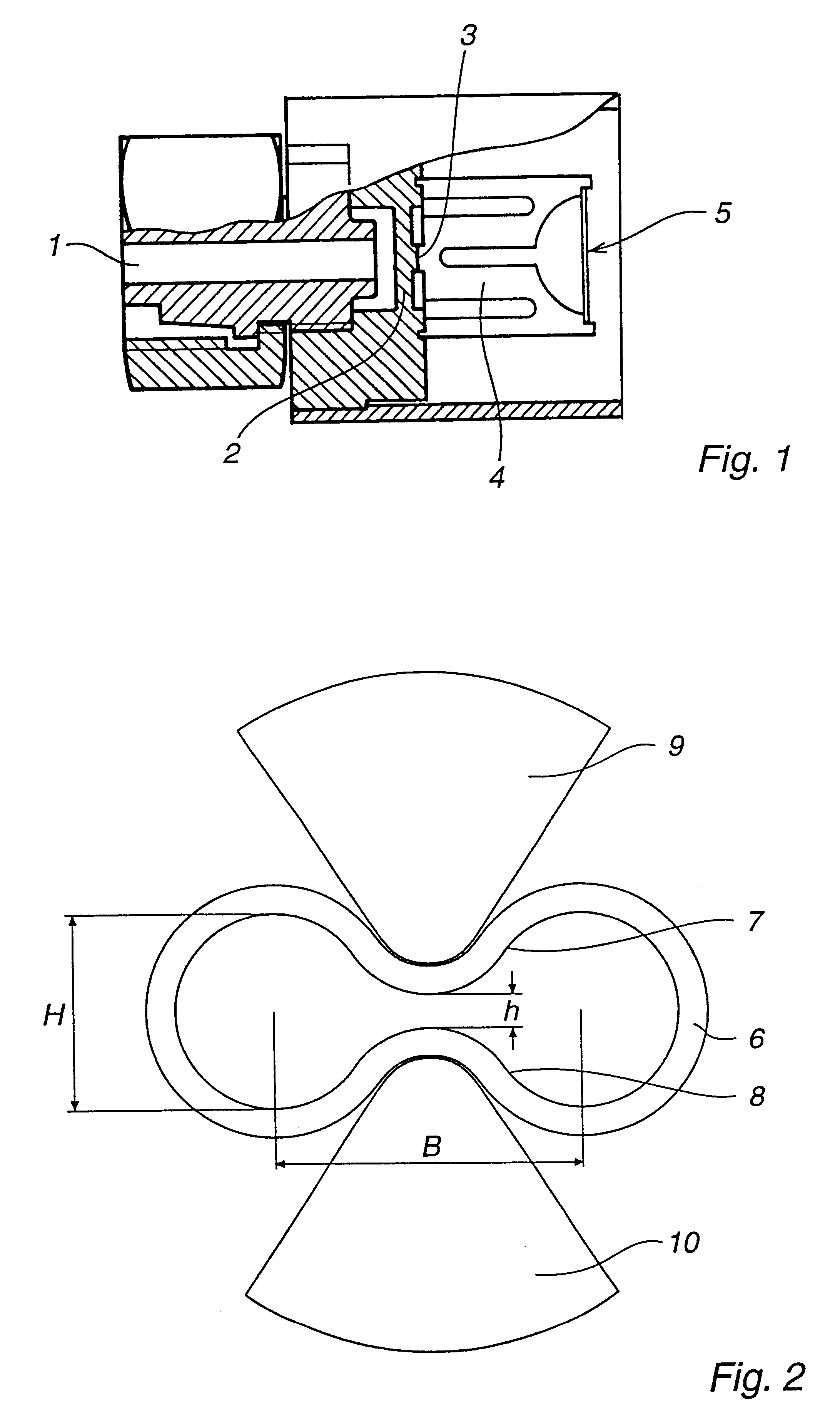
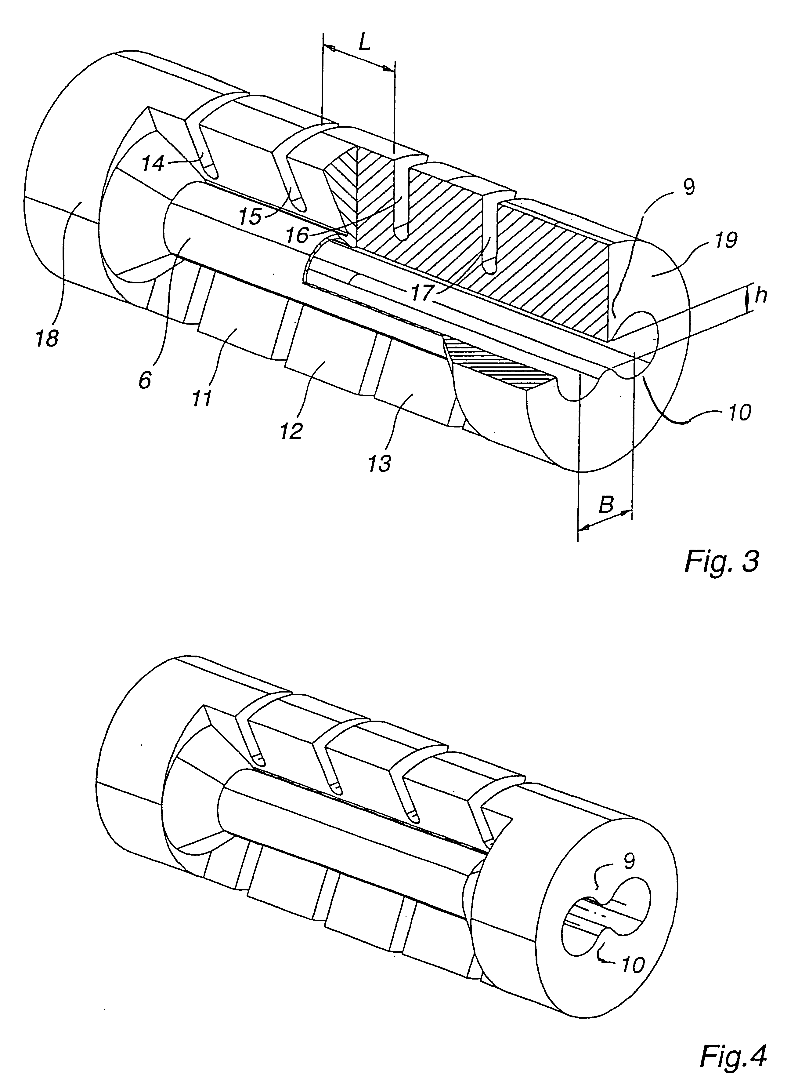
An embodiment of a pressure sensor for gas pressure in a cylinder of a combustion engine is shown in FIG. 2 The walls of the measuring section of the tube 6 are so shape that the internal cross section is like that of an hourglass, consisting of two circles connected to each other by means of a waist section. In an alternative embodiment the walls of the tube can also be attached to be beams 9, 10, as shown in FIG. 3. The outer surface of the beam of section 12 is attached to a rigid force measuring means, as shown for example FIG. 5.

In the embodiment shown in FIG. 2, 3, 4 and 5 the dimension h, the distance between measuring surface, is reduce by means of the waist in the hourglass shape. In the axial direction the pressure sensor tube 6 has been divided up into three sections 11, 12, 13 between the two end sections 18, 19 by means of four slots 14, 15, 16, 17 in the beams 9, 10 shown in FIG. 3 which are on either side of the measuring surfaces 7, 8 shown in FIG. 2. The measuring s...


PUM

PropertyMeasurementUnit
temperatureaaaaaaaaaa
pressureaaaaaaaaaa
axial lengthaaaaaaaaaa

Abstract

Pressure sensor for measurement of gas pressure in a cylinder of a combustion engine, including a tube shaped in cross section as an hourglass. In the axial direction the tube consists in part of a section connected to the cylinder and open to the cylinder, in part of a measuring section and in part of a final section the end of which is closed. The measuring section of the tube is shaped so that in the tubes axial direction two parallel measuring surfaces are established against which are two beams connected to force transferring yokes arranged to influence force measuring organs for the determination of the force with which the gas pressure influences the parallel measuring surfaces of the tube. In this pressure sensor and other embodiments the influences of temperature fluctuations and any shunting effects of the material of the measuring tube are reduced to a minimum.

Description

TECHNICAL AREAThe present invention concerns a pressure sensor for the continuous measurement of gas pressure inside the cylinders of a combustion engine. The pressure sensor is consequently placed in a very severe environment with high pressure of several hundred bar and a temperature of up to 1000.degree. C. Continuous measurement to be able to determine the pressure distribution during every working cycle in the combustion engine places heavy demands on the dynamic response of the pressure sensor to rapid processes.The greatest area of use for continually measuring pressure sensors is in very large combustion engines which are operated at relatively low revolutions per minute. Such motors are used for example as ships engines and as stationary engines for driving electrical generators and gas compressors.Because of the growing demands for reduced consumption of fuel and continually increasing environmental demands on the chemical composition of exhaust gases the requirement to mo...

Claims


Application Information

Patent Timeline
Patent Type & Authority Patents(United States)
IPC IPC(8): G01L23/00G01L9/00G01L19/04G01L23/14G01L23/22G01L9/16
CPCG01L9/0026G01L23/145G01L19/04G01L23/08
Inventor GUSTAFSSON, PARKOLAVCIC, PAVELLIFVENBORG, ULF
Owner ABB (SCHWEIZ) AG
Learn More