Crank mechanism of reciprocating internal combustion engine of multi-link type
a multi-link type, crank mechanism technology, applied in the direction of machines/engines, positive displacement engines, mechanical devices, etc., can solve the problems of difficult to provide the first and second connecting pins
- Summary
- Abstract
- Description
- Claims
- Application Information
AI Technical Summary
Benefits of technology
Problems solved by technology
Method used
Image

Examples
first embodiment
Referring to FIG. 1 to FIGS. 8A and 8B, there is shown a crank mechanism 100 which is the present invention.
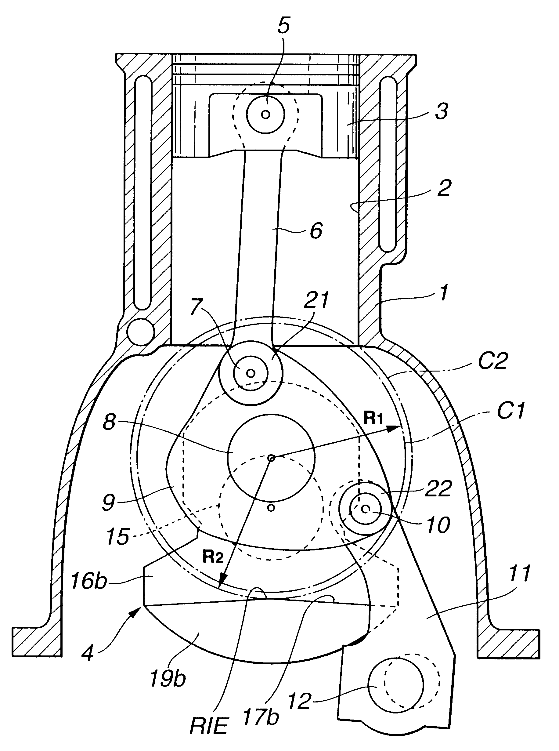
In FIG. 1, a reciprocating internal combustion engine is shown to which the crank mechanism 100 of the first embodiment is practically applied. The engine generally comprises a cylinder block 1 having a plurality of cylinders 2 which are juxtaposed. Each cylinder 2 has a piston 3 slidably disposed therein. A crankshaft 4 extends axially below the cluster of the pistons 3, which is rotatably held by the cylinder block 1.
An upper link 6 extends downward from each of the pistons 3. That is, the upper link 6 has an upper end pivotally connected to the piston 3 through a piston pin 5. The upper link 6 has a lower end pivotally connected to a lower link 9 through a first connecting pin 7. The lower link 9 is swingably disposed on a crank pin 8 of the crankshaft 4 and has one end to which an upper end of a control link 11 is pivotally connected through a second connecting pin 10. A l...
third embodiment
Referring to FIGS. 10 and 11, there is shown a crank mechanism 300 of the present invention.
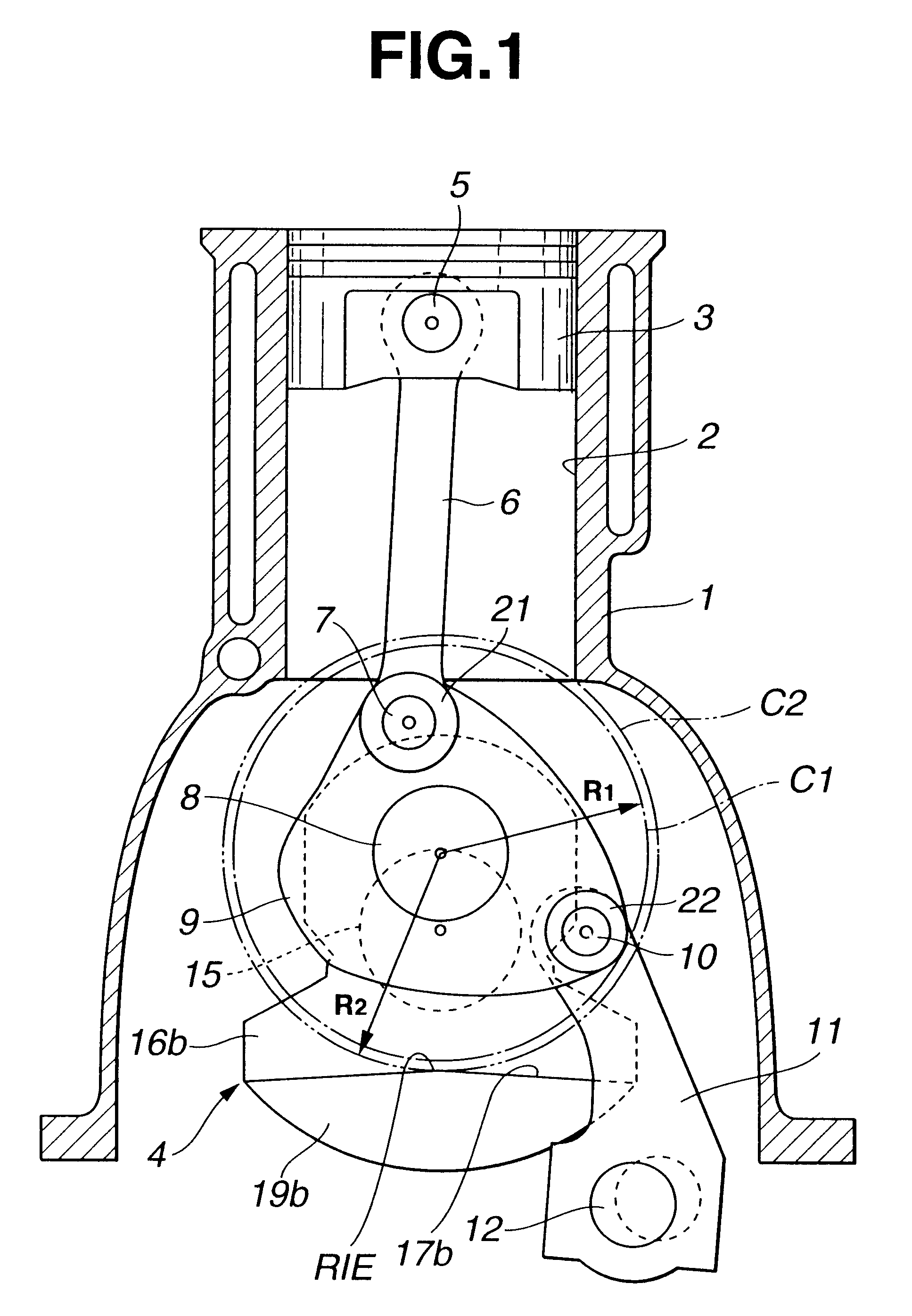
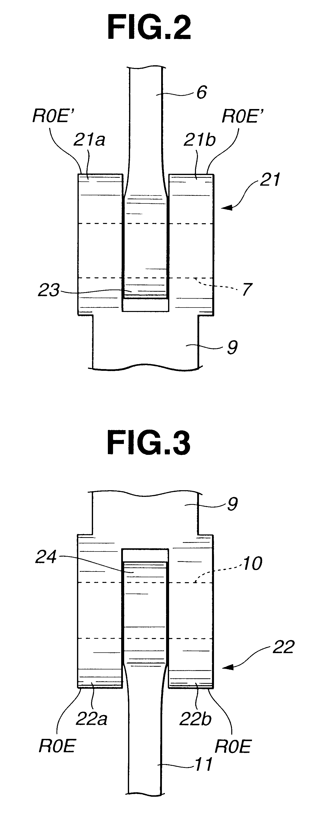
As is seen from FIG. 11, in this third embodiment, the axial dimension (or thickness) of each of the second and first forked portions 22 and 21 of the lower link 9 is equal to that of the major central portion of the lower link 9 and slightly smaller than the distance between the projected inner surfaces 19a and 19b of the counterweights 16a and 16b. As shown, each of the second and first connecting pins 10 and 7 incorporated with the second and first forked portions 22 and 21 has a length smaller than the distance between the mutually facing bottom surfaces of the recesses 17a and 17b. However, each connecting pin 10 or 7 has axially opposed ends projected from the support arms 22a and 22b (or, 21a and 21b). The projected ends are equipped with respective snap rings 31a and 31b for holding the connecting pin 10 or 7 in position.
As is shown in FIG. 11, in this third embodiment, the radius R1 ...
fourth embodiment
Referring to FIG. 13, there is shown a crank mechanism 400 of the present invention.
As is seen from this drawing, the lower link 9' employed in this fourth embodiment 400 is different in shape from the lower link 9 used in the above-mentioned first, second and third embodiments 100, 200 and 300. That is, the lower link 9' swingably disposed on the crank pin 8 comprises a first forked portion 21 to which a lower end of the upper link 6 is pivotally connected through the first connecting pin 7 and a second forked portion 22 to which an upper end of the control link 11 is pivotally connected through the second connecting pin 10. However, the second forked portion 22 is formed on a leading end of an arm 9'a extending from a major portion of the lower link 9'. This unique shape of the lower link 9' is thought out by taking a load balance between the first and second forked portions 21 and 21 into consideration. That is, as is shown in the drawing, if a distance between the axis of the cr...
PUM
 Abstract
Description
Claims
Application Information
 - R&D
- Intellectual Property
- Life Sciences
- Materials
- Tech Scout
- Unparalleled Data Quality
- Higher Quality Content
- 60% Fewer Hallucinations
Browse by: Latest US Patents, China's latest patents, Technical Efficacy Thesaurus, Application Domain, Technology Topic, Popular Technical Reports.
© 2025 PatSnap. All rights reserved.Legal|Privacy policy|Modern Slavery Act Transparency Statement|Sitemap|About US| Contact US: help@patsnap.com