Magnetic resonance imaging device and method therefor

a magnetic resonance imaging and magnetic resonance technology, applied in the direction of diagnostic recording/measuring, measuring using nmr, instruments, etc., can solve the problem of real time loss in imaging, and achieve the effect of high-quality temperature change distribution images

Inactive Publication Date: 2003-05-20
HITACHI MEDICAL CORP
View PDF3 Cites 71 Cited by
  • Summary
  • Abstract
  • Description
  • Claims
  • Application Information

AI Technical Summary

Benefits of technology

is to solve these problems and to provide hig...

Problems solved by technology

Then the real ti...

Method used


Image

  • Magnetic resonance imaging device and method therefor
  • Magnetic resonance imaging device and method therefor
  • Magnetic resonance imaging device and method therefor

Examples


Embodiment Construction

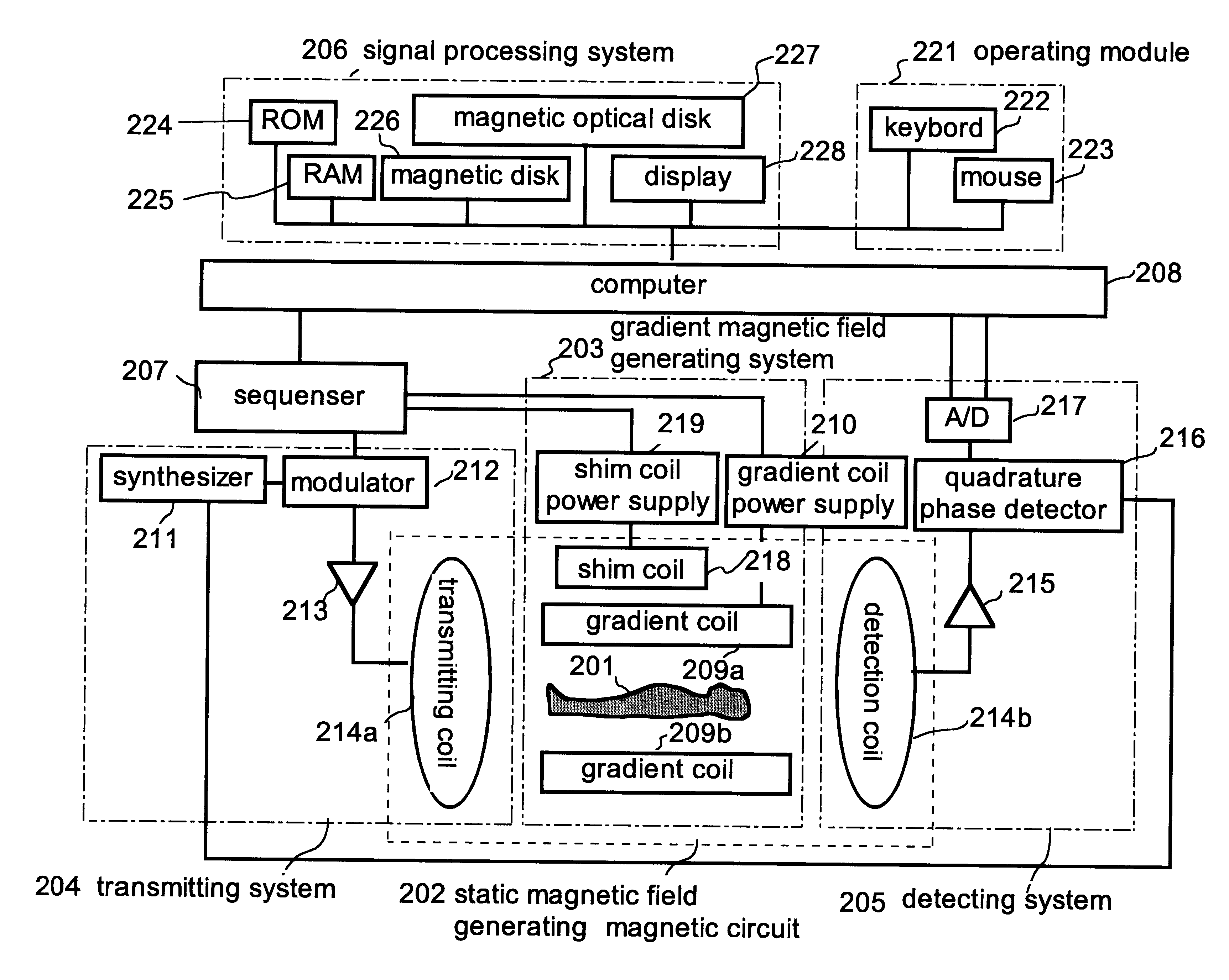
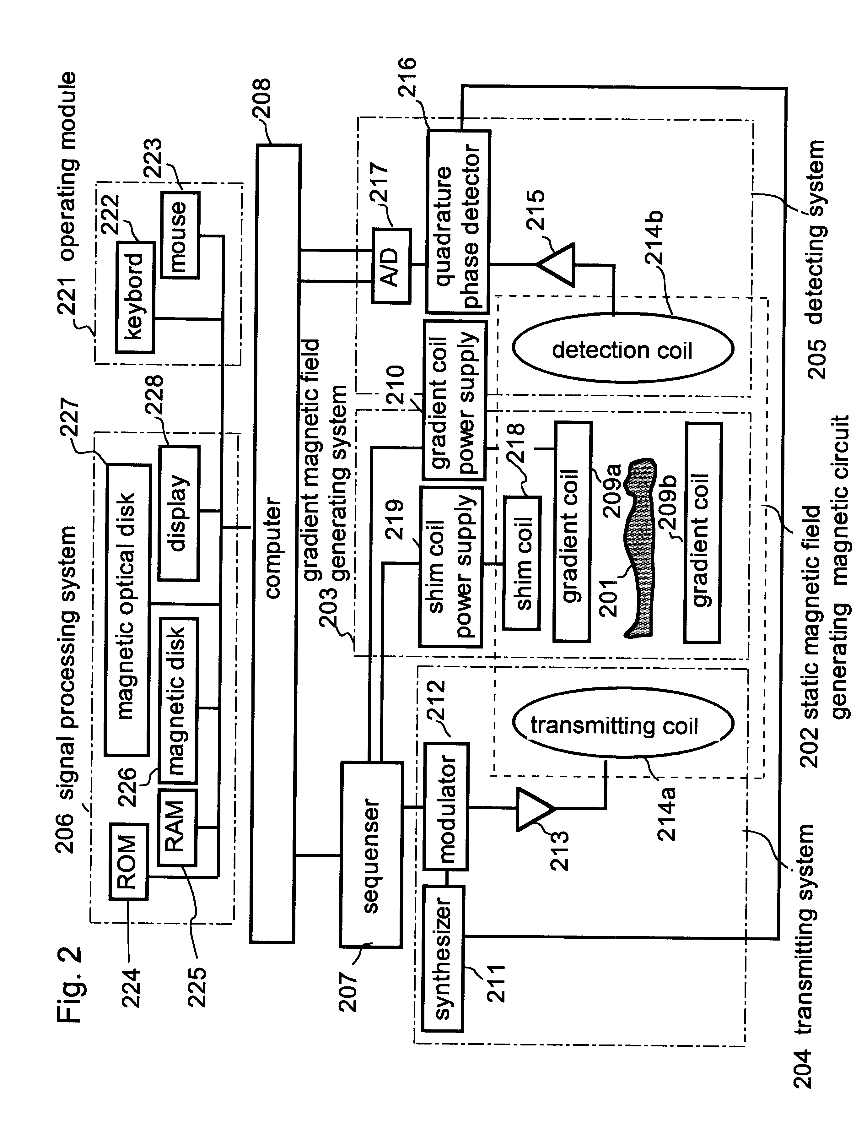
One embodiment of the present invention will now be explained referring to FIG. 1 to FIG. 11. At first, the composition of MRI apparatus in the embodiment is explained in FIG. 2. An MRI apparatus comprises magnetic circuit 202 for generating a static magnetic field having an electromagnet or a permanent magnet for generating an uniform static magnetic field H0 in interior of the object to be examined 201, gradient magnetic field coil 209 for generating gradient magnetic field Gx, Gy, Gz, of which the intensity varies linearly to the three direction x, y, and z perpendicular to the object 201, transmitting coil 214a for transmitting a high frequency magnetic field to the object 201, detecting coil 214b for detecting a nuclear magnetic resonance signals generated from the object 201, and sequencer 207 for making generation of a gradient magnetic field or a high frequency pulse at a predetermined timing, computer 208 for performing various kinds of processing such as controlling of seq...


PUM


Abstract

Variations in spatial phase distribution due to static magnetic field changes are corrected based on phase variations at points, specifically, at three points or a plurality of points selected by ROI, in an area where no temperature change is encountered. And a temperature distribution image is determined by using a spatial phase distribution reflecting only temperature changes after the correction, thereby high-accuracy temperature distribution image information is provided.

Description

This invention relates to a magnetic resonance imaging apparatus (hereinafter this is referred to MRI), especially to technology being suitable for measuring an image of a temperature distribution in a living body with a MRI apparatus.BACKGROUND OF THE ARTRecently interventional MRI (hereinafter, this is referred to IV-MRI) using an MRI apparatus as a surgery monitor is attended. In a therapy method performed by using IV-MRI, there is a laser treatment, a drag injection of ethanol or the like, an RF irradiation excision, and a low temperature treatment. In these treatments, MRI plays a role for guiding a needle or a narrow tube to a diseased part by real time imaging, or visualizing a change of tissues in said treatments, or monitoring a limited part in application of heating or cooling treatment, or the like. A typical application for IV-MRI includes an imaging of the temperature distribution within the body when said laser treatment is performed.Imaging method of the temperature d...

Claims


Application Information

Patent Timeline
IPC IPC(8): G01R33/54G01R33/565A61B5/055
CPCG01R33/56563
Inventor KOMURA, KAZUMITAKAHASHI, TETSUHIKO
Owner HITACHI MEDICAL CORP
Why Eureka
Try Eureka