
Mount for a shock absorber

a technology for shock absorbers and mounting brackets, which is applied in the direction of shock absorbers, manufacturing tools, transportation and packaging, etc., can solve the problems of shock absorber connected to the mounts achieving the wear limit, and the various connecting means in question will almost certainly not be properly aligned with each other, and the shock absorber connected to the mounts will reach the wear limit. , the effect of functional disadvantag

Inactive Publication Date: 2003-06-03
ZF FRIEDRICHSHAFEN AG
View PDF4 Cites 18 Cited by
  • Summary
  • Abstract
  • Description
  • Claims
  • Application Information

AI Technical Summary

Benefits of technology

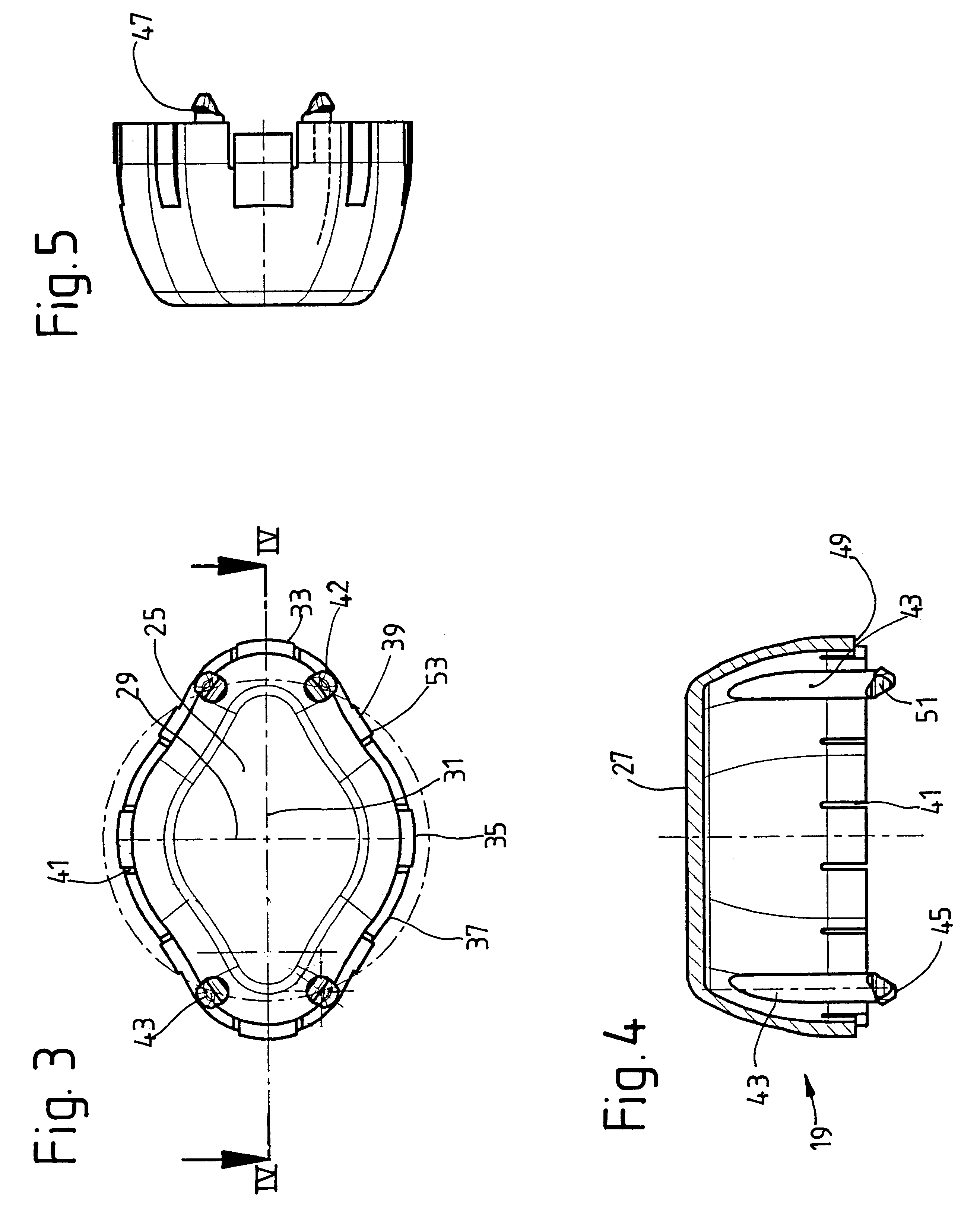
It is also provided that the working, torque-transmitting connection is formed by at least one extension on the cap, which engages with the mount. This working, positive-locking connection ensures that the various connecting means are positioned with a high degree of positional accuracy with respect to each other. In addition, higher torques can be transmitted.
The increased load on the cap in the area of the elastic wall parts is taken into account by making the elastic wall parts thicker, at least over part of their area, than the adjacent wall areas.

Problems solved by technology

In regard to the installation of a shock absorber, for example, there is the problem that at least one connecting means on the shock absorber must be engaged with another connecting means on the body of the vehicle.
When an assembly device introduces the shock absorber into the body, it can be assumed that the various connecting means in question will almost certainly not be properly aligned with each other.
A significant disadvantage of this rubber-metal mount is that, although the shape of the rubber-metal mount may well be suitable for automated assembly, it suffers otherwise from functional disadvantages in certain situations.
It may happen that the shock absorber connected to the mount reaches its wear limit and must be replaced.

Method used


Image

  • Mount for a shock absorber
  • Mount for a shock absorber
  • Mount for a shock absorber

Examples


Embodiment Construction

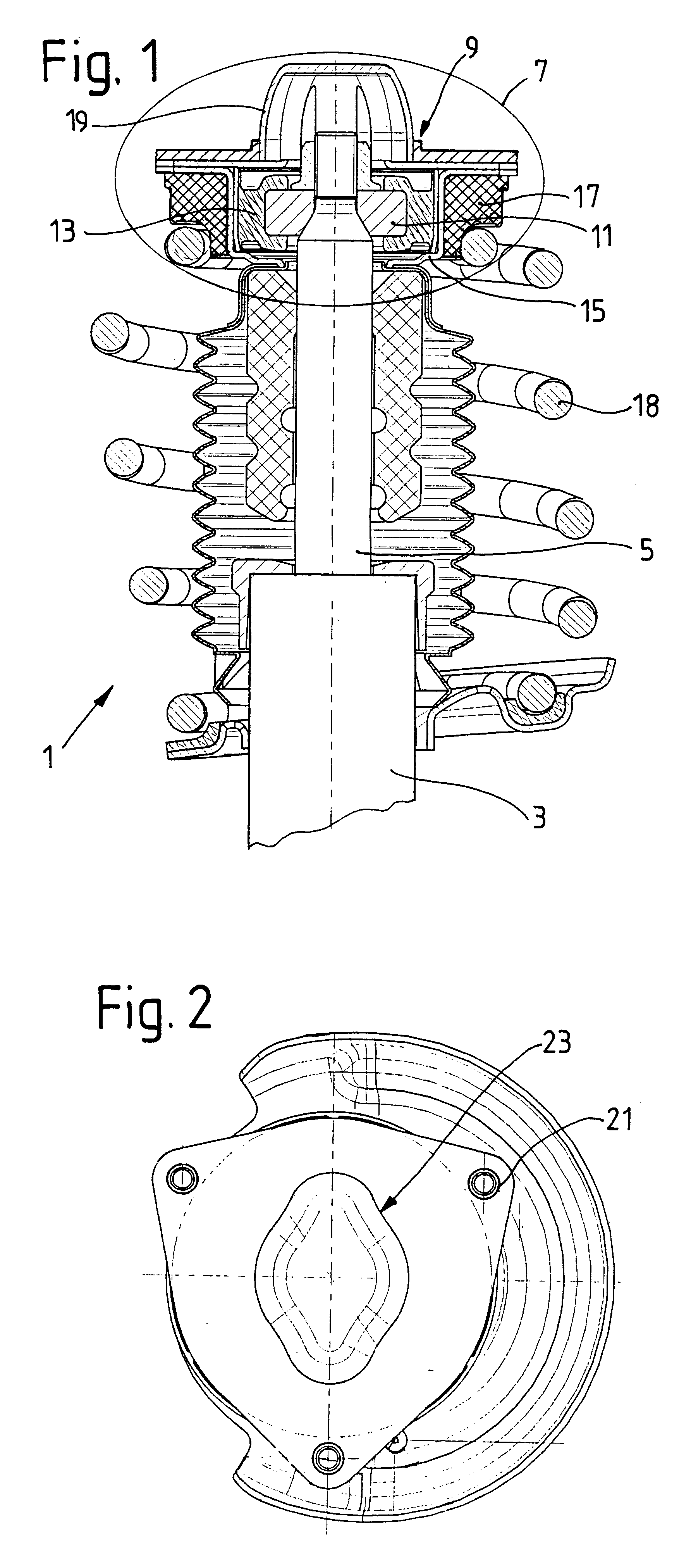
FIG. 1 shows the top end of a shock absorber 1, which comprises a cylinder 3, in which a piston rod 5 is supported with freedom of axial movement. At its outer end, the piston rod has a mount 7, by which it is connected to a vehicle, of which only a mounting hole 9 inside a support element is shown. A mounting hole of this type can be provided in, for example, an inside fender of the vehicle.

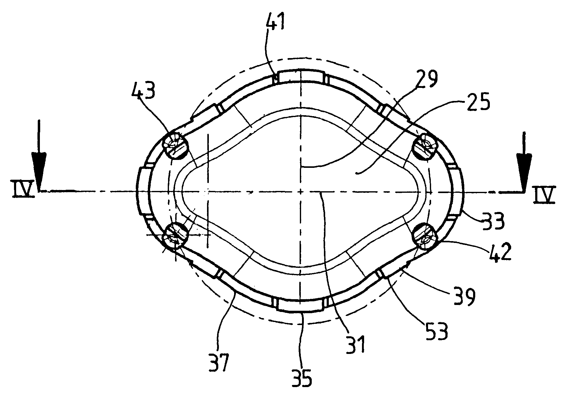
The mount 7 comprises a support 11, which is at least partially surrounded by a spring element 13. The spring element is enclosed in turn by a mount housing 15, against the outside of which a spring pad 17 for a vehicle suspension spring 18 is supported. The entire mount is covered by a cap 19.

FIG. 2 shows a top view of the mount 7. The mount housing 15 contains connecting means 21 in the form of holes for fastening screws for attachment to the vehicle. During the assembly process, these holes must be brought into alignment with connecting means on the vehicle (not shown). For this purpose, the ...


PUM


Abstract

Mount for a shock absorber includes a cap in working torque-transmitting connection with the entire mount. The twisting surface, which is in working connection with an opposing surface on the vehicle at least during the installation of the shock absorber in a mounting hole in the vehicle. The twisting surface and the opposing surface ensure the rotational alignment of the connecting means on the mount side with the connecting means on the vehicle side.

Description

1. Field of the InventionThe invention pertains to a mount for a shock absorber, the mount having a twisting surface which engages an opposing surface on a vehicle at least during installation in a mounting hole of the vehicle, the twisting surface and the opposing surface ensuring the rotational alignment of the connecting means on the mount and the connecting means on the vehicle.2. Description of the Related ArtIQ The increasing use of automation in vehicle assembly means that the individual parts of the vehicle must be designed in such a way that they can be assembled as easily as possible by machine. In regard to the installation of a shock absorber, for example, there is the problem that at least one connecting means on the shock absorber must be engaged with another connecting means on the body of the vehicle. When an assembly device introduces the shock absorber into the body, it can be assumed that the various connecting means in question will almost certainly not be proper...

Claims


Application Information

Patent Timeline
Patent Type & Authority Patents(United States)
IPC IPC(8): B60G15/06B60G13/00B60G15/00F16F9/54B23P19/00B60G15/07
CPCB60G13/003B60G15/067F16F9/54B60G2200/46B60G2202/312B60G2204/124B60G2204/128B60G2204/4304B60G2204/44B60G2204/45021B60G2204/61B60G2206/931B60G2204/43B60G15/07
Inventor ZIETSCH, ANDREAS
Owner ZF FRIEDRICHSHAFEN AG
Learn More