High capacity ion cyclotron resonance cell

a cyclotron resonance, high-capacity technology, applied in the direction of mass spectrometry, instruments, separation processes, etc., can solve the problems of space charge-induced shift of the cyclotron frequency, limited ft-icr mass measurement accuracy, and significant harmonics in the acquired signal, so as to minimize the space charge-induced shift

Inactive Publication Date: 2003-06-03
THERMO FINNIGAN
View PDF5 Cites 14 Cited by
  • Summary
  • Abstract
  • Description
  • Claims
  • Application Information

AI Technical Summary

Benefits of technology

It is a further object of the present invention to provide an ICR cell in which space charge-induced shifts are minimized.

Problems solved by technology

It has been recently demonstrated that one of the primary limitations to obtaining accurate mass measurement for FT-ICR is space charge-induced shifts of the cyclotron frequency.
The primary drawback to a non-zero initial magnetron radius is that the acquired signal will contain significant harmonic content and other modulations of the fundamental signal (Chen et al., "An off-center cubic ion trap for Fourier transform ion cyclotron resonance mass spectrometry", Int. J. Mass Spectrom.
The primary disadvantage of the two-electrode trap is the severe axial ejection caused by the parametric excitation and significant axial fields.

Method used


Image

  • High capacity ion cyclotron resonance cell
  • High capacity ion cyclotron resonance cell
  • High capacity ion cyclotron resonance cell

Examples


Embodiment Construction

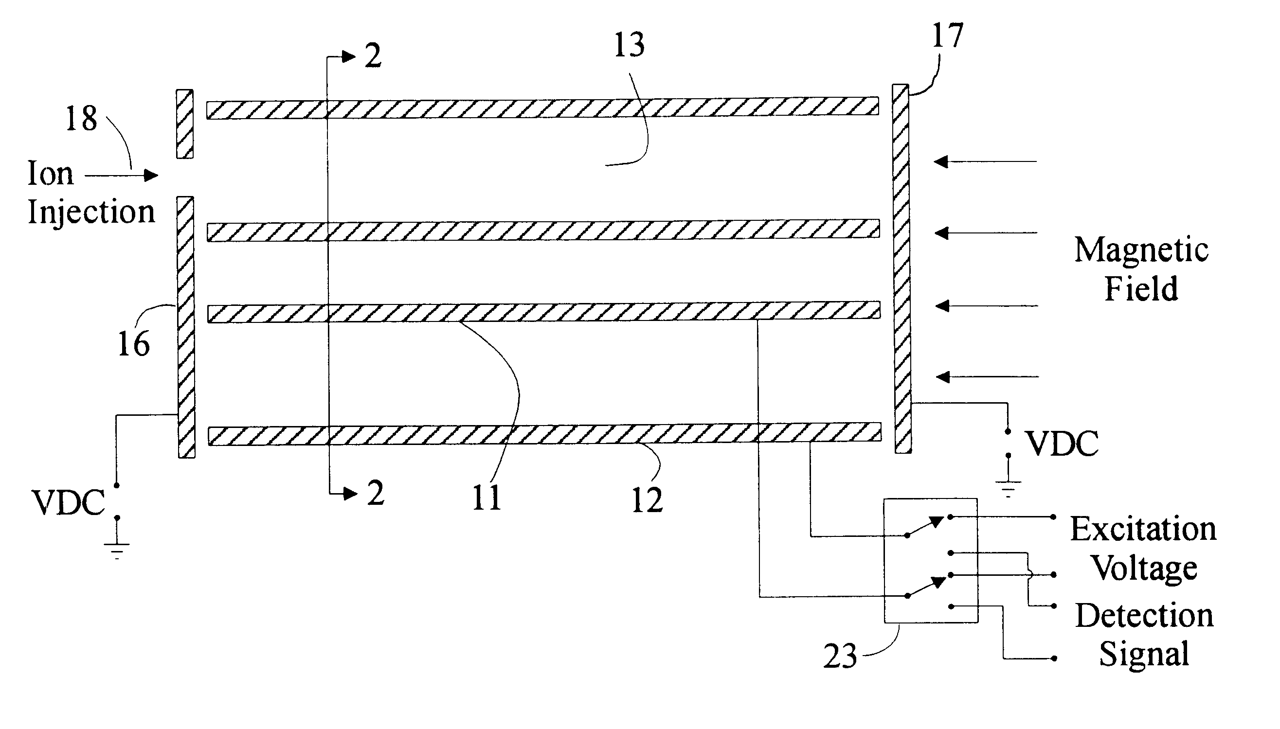
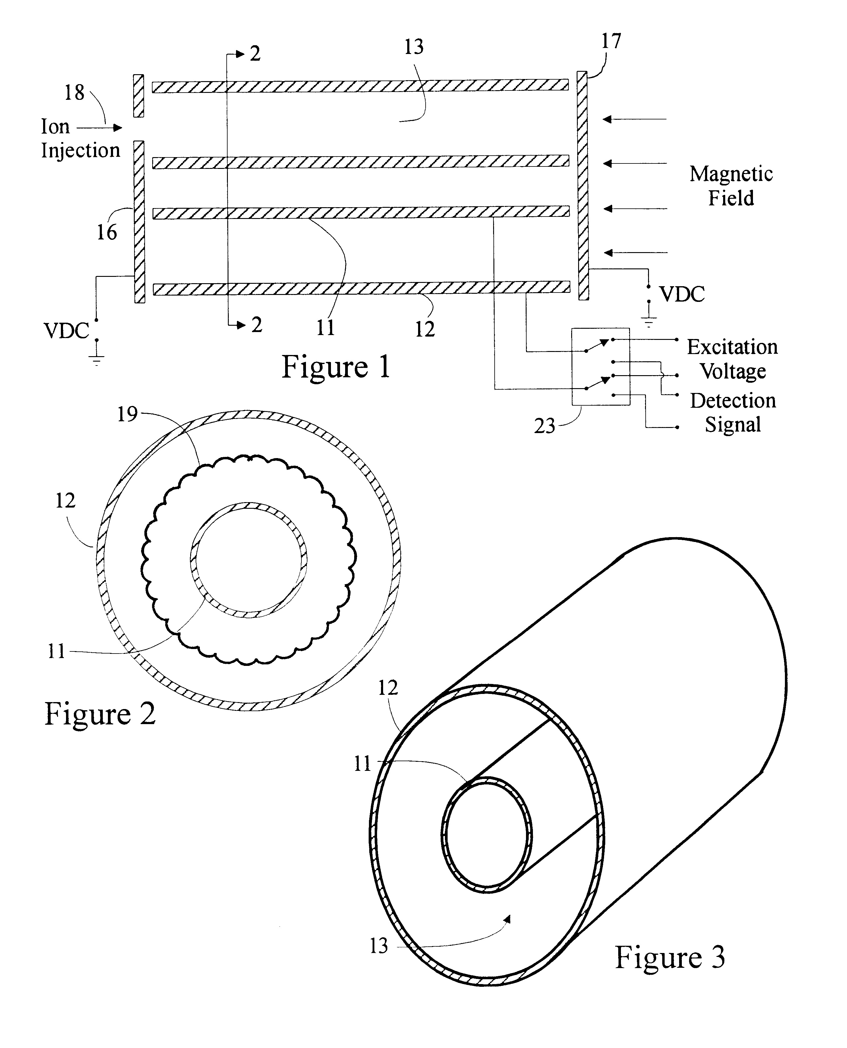
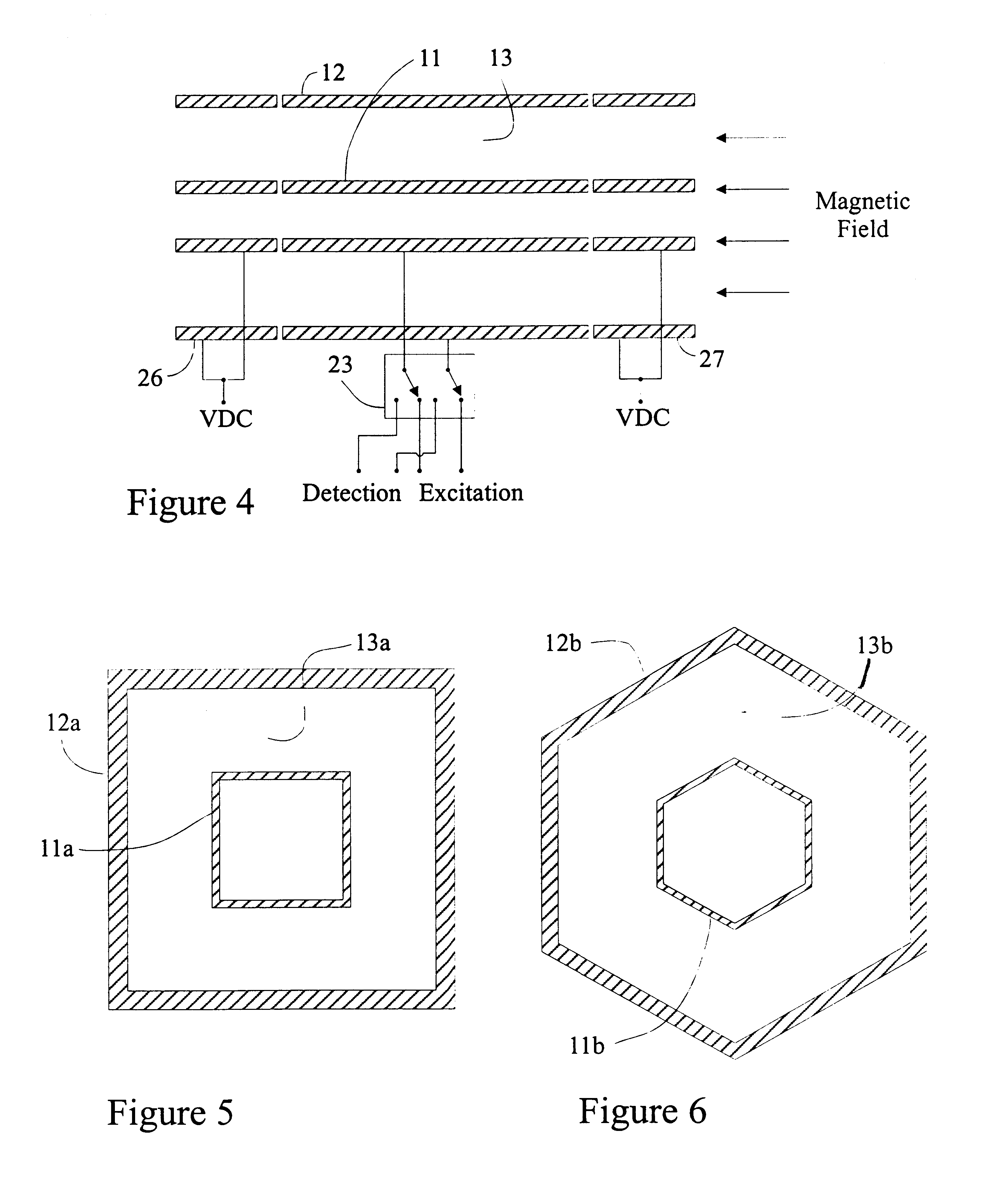
Referring to FIGS. 1, 2 and 3, an ICR cell in accordance with one embodiment of the invention is illustrated. The cell includes spaced hollow cylindrical electrodes 11 and 12 which define an annular trapping space 13. Although shown as a hollow electrode, the electrode 11 need not be a hollow electrode.

Trapping electrodes 16 and 17 perpendicular to the magnetic field are spaced from the ends of the cylindrical electrodes and, as is well known, serve to confine ions within the trapping region 13. Ions are introduced into the region 13 by injecting off-axis from a suitable external source as indicated by the arrow 18. The off-axis injection provides a component of ion travel which is perpendicular to the magnetic field, and gives rise to magnetron motion as indicated by the curve 19, FIG. 2, in which the ions orbit around the central cylinder. This orbiting reduces the axial velocity of the ions and provides a greater dwell time within the ion trap. The ion trap is shown disposed in a...


PUM


Abstract

An ion cyclotron resonance cell having a large ion trapping volume is described. The cell includes elongated spaced concentric electrodes having a common axis in which the trapping volume is the space between the electrodes. The cell may also include trapping electrodes disposed at the ends of the elongated concentric electrodes.

Description

This invention relates generally to an ion cyclotron resonance (ICR) cell, and more particularly to an ICR cell with large ion storage capacity.Ion cyclotron resonance is well known and has been employed in numerous spectroscopy devices and studies. Generally, these devices store the ions to be analyzed in cells of various configurations which are disposed in a uniform magnetic field. Gaseous ions in the presence of the uniform magnetic field are constrained to move in circular orbits in a plane perpendicular to the field (cyclotron oscillations). The ions are not constrained in their motion parallel to the field. As a consequence, various cell configurations have been adopted to retain the ions within the cell. For example, the cell may include end plates which have dc voltages applied thereto, or it may be of an open cell design such as described by Beu et. al., "Open trapped ion cell geometries for FT / ICR / MS, Int. J. Mass Spectrom. Ion Processes, 112 (1992), 215-230. Another cell...

Claims


Application Information

Patent Timeline
Patent Type & Authority Patents(United States)
IPC IPC(8): H01J49/38H01J49/34
CPCH01J49/38
Inventor SENKO, MICHAEL
Owner THERMO FINNIGAN
Why Eureka
Try Eureka