Vehicular sensors

a technology of vehicle sensor and sensor body, applied in the direction of brake cylinder, instrument, force/torque/work measurement apparatus, etc., can solve the problems of inability to readily adapt to various types of vehicles, high cost of after-market electronic systems, and inability to use them widely

Inactive Publication Date: 2003-07-22
CALSPAN CORP
View PDF48 Cites 81 Cited by
  • Summary
  • Abstract
  • Description
  • Claims
  • Application Information

AI Technical Summary

Problems solved by technology

Electronic parametric monitoring devices that warn of an out-of-tolerance condition to date have not been widely used and have not been generally installed by original equipment manufacturers ("OEM") on new commercial vehicles.
Some after-market electronic systems tend to be expensive, not readily compatible with various types of vehicles, and difficult to install.
Because the pushrods have a limited length of travel, as the brake shoes / pads wear, at some point the pushrod cannot move enough to actuate the brakes fully, resulting in reduced braking force.
However, if the driver fails to manually readjust the brakes regularly, or if the automatic adjuster does not function properly the brakes will eventually be in an OOS condition.
Prior art methods of monitoring braking systems can entail time-consuming and dirty work.
Although brake inspection is part of the driver's daily vehicle inspection procedure, the inconvenience involved in monitoring braking systems results in brake stroke measurements often not be taken as often as desirable.
A disadvantage of this system is that two persons are generally required to use this system; one person to press the brake pedal in the cab and one to visually inspect each brake actuator device.
Excessive steering lash results in the driver having to adjust the steering column position often and can cause excessive wear to the front tires (i.e., the steerable wheels).
It can contribute to driver fatigue and impair the driver's ability to precisely control the vehicle and can also lead to premature tire wear.

Method used


Image

  • Vehicular sensors
  • Vehicular sensors
  • Vehicular sensors

Examples


Embodiment Construction

The particulars shown herein are by way of example and for purposes of illustrative discussion of the embodiments of the present invention only and are presented in the cause of providing what is believed to be the most useful and readily understood description of the principles and conceptual aspects of the present invention. In this regard, no attempt is made to show structural details of the present invention in more detail than is necessary for the fundamental understanding of the present invention, the description taken with the drawings making apparent to those skilled in the art how the several forms of the present invention may be embodied in practice.

A. BRAKE STROKE SENSOR

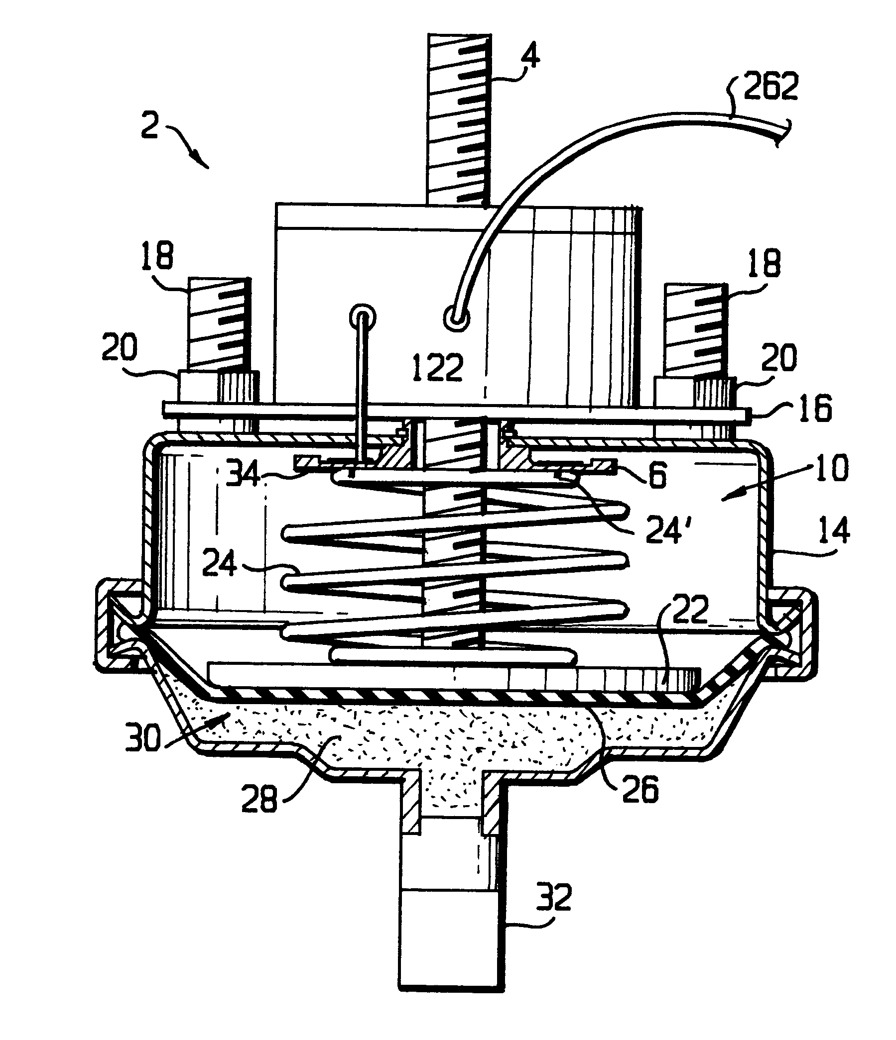
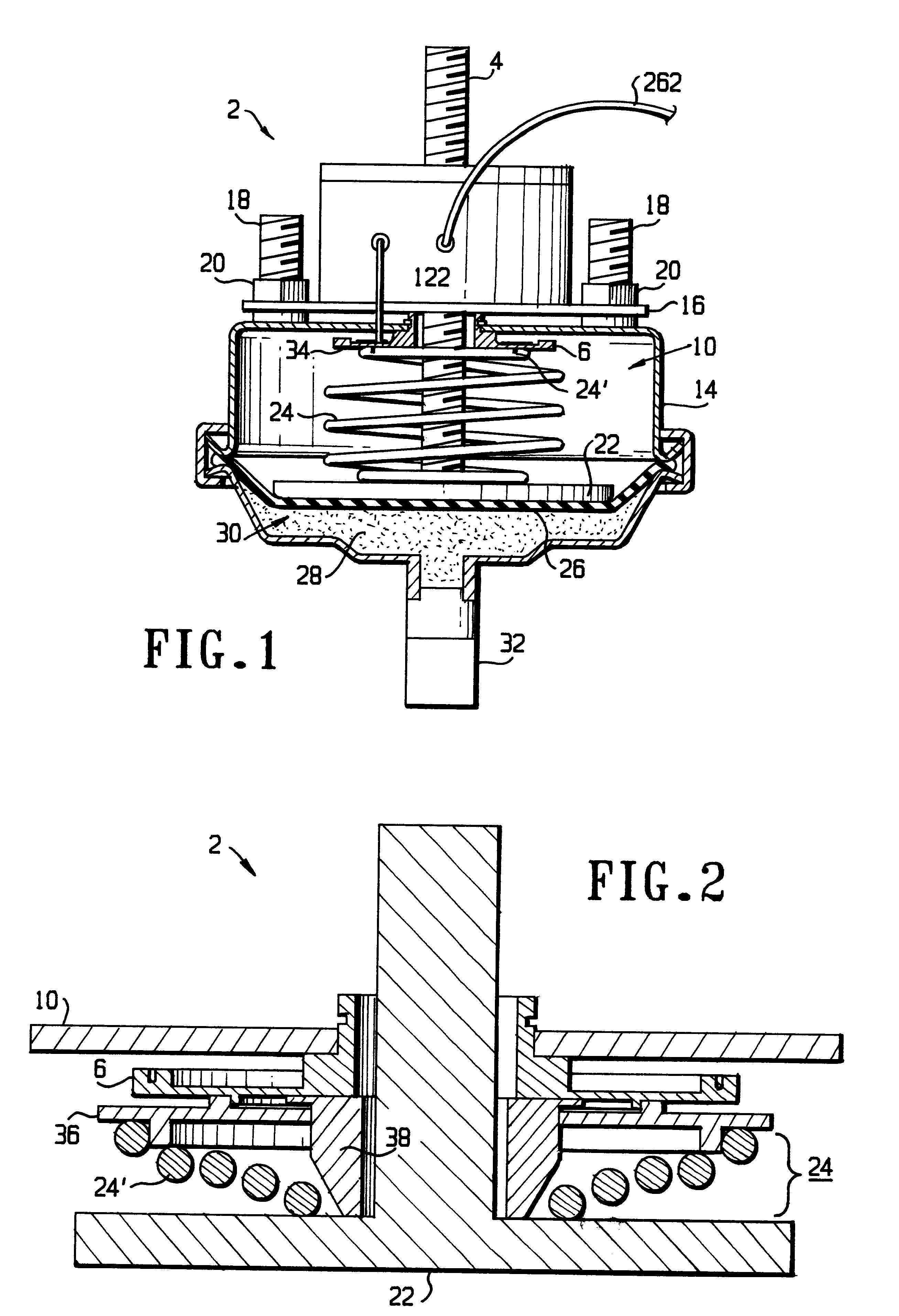
FIG. 1 illustrates a brake actuator system with a brake stroke system installed. A brake sensor 2 for determining the position of a brake actuator's pushrod 4 at any point throughout its entire range of motion includes a force-sensing assembly 6 and a brake sensor control / communications assembly 8. The for...


PUM


Abstract

A brake stroke sensor and an steering sensor are individually and collectively provided. A brake stroke sensor includes a force-receiving plate, a second plate movable relative to the force-receiving plate, a spring disposed between the plates and operatively connected to the pushrod, a strain gauge bridge mounted on the force-receiving plate and a microcontroller capable of converting the strain gauge bridge signal into digital data. A steering sensor includes a mechanical interface operatively connected to a nonmoving member and a moving member, an encoder capable of transforming the rotational motion of the mechanical interface into an electrical signal, and a microcontroller capable of calculating, from the electrical signal, a count indicative of the relative positions of the members. A combined brake stroke and steering sensor may include individual and common elements of both the brake stroke and steering sensors described above. The brake stroke, steering sensor and combined brake stroke and steering sensor may utilize a modem for transmitting data to a system controller over an electrical bus.

Description

1. Field of the InventionThe present invention relates to the field of vehicular sensor systems.2. Discussion of Background InformationIt is desirable to maintain and monitor the proper functioning of a vehicle's brake and steering systems to enhance the safety of the driver and general public, and to help determine whether these systems meet federal safety standards for correct operation. If either the braking or steering systems of a commercial vehicle do not meet federal operational requirements, the commercial vehicle can, be placed out-of-service ("OOS"), until the problematic system is repaired and returned to acceptable operational limits.Electronic parametric monitoring devices that warn of an out-of-tolerance condition to date have not been widely used and have not been generally installed by original equipment manufacturers ("OEM") on new commercial vehicles. Some after-market electronic systems tend to be expensive, not readily compatible with various types of vehicles, a...

Claims


Application Information

Patent Timeline
Patent Type & Authority Patents(United States)
IPC IPC(8): B60T17/18B60T17/00B60T17/08B62D15/00B62D15/02B60T17/22F16D66/00
CPCB60T17/08B60T17/221B62D15/02F16D66/00F16D2066/003
Inventor FUGLEWICZ, DANIEL P.KEPPLER, TODD H.NOWAK, CHRIS J.SCHABEL, DAVID G.
Owner CALSPAN CORP
Why Eureka
Try Eureka