Echo cancellation device for cancelling echos in a transceiver unit

a transceiver unit and echo cancellation technology, which is applied in the direction of transmission, substation equipment, instruments, etc., can solve the problems of large occupied resources of the transmitting unit tr, unnatural voice, and inability to achieve good compression ratio of parameters and residual signals

Inactive Publication Date: 2003-07-22
TELEFON AB LM ERICSSON (PUBL)
View PDF26 Cites 97 Cited by
  • Summary
  • Abstract
  • Description
  • Claims
  • Application Information

AI Technical Summary

Benefits of technology

The above described aspects of the present invention can also be used in combination. That is, the first and second aspect, the first and third aspect, the second and third aspect and the first, second and third aspect may be combined. Further advantageous embodiments and improvements of the invention can be taken from the attached dependent claims. It should also be noted that the invention can comprise embodiments resulting from a combination of features separately claimed in the claims and/or described in the specification inc

Problems solved by technology

However, in practice the main or basic echo cancellation by using the transfer function estimator and the subtractor cannot remove the returning signal completely.
Actually, the voice will sound unnatural due to the excitation signals.
However, the transmission of parameters and the residual signal would not correspond to a good compression ratio.
This required bandwidth can be quite large and can thus cause the resources of the transmitting unit TR to be occupied to a large extent during the transmission of speech.
The coding of quite irrelevant background noise with the same bandwidth as used for the coding of the speech would be quite a waste of resources in the transmitting unit TR

Method used


Image

  • Echo cancellation device for cancelling echos in a transceiver unit
  • Echo cancellation device for cancelling echos in a transceiver unit
  • Echo cancellation device for cancelling echos in a transceiver unit

Examples


first embodiment

The purpose of the spectral content determining means is to monitor at least one of the signals entering the unit. Preferably, the far end signal spectral content is determined on the basis of the signal RFE' such that the determined spectral content will be close to that of the residual echo signal. Before giving further examples as to how the spectral content determining means determines the spectral content, some general steps of the method of the first embodiment shown in FIG. 5 will be considered.

In a first step for the attenuation of the far end signal, i.e. the residual echo in the output TNE' of the adder ADD, least one signal relating to the far end signal RFE is taken, preferably REF or REF'. This signal is hereinafter denoted with "X".

In a second step a model of the spectral content of the selected signal X is computed by the spectral content determining means CTL. This model of the spectral content is denoted with "A" and can be determined on the basis of

a) a parametric ...

second embodiment

OF THE INVENTION

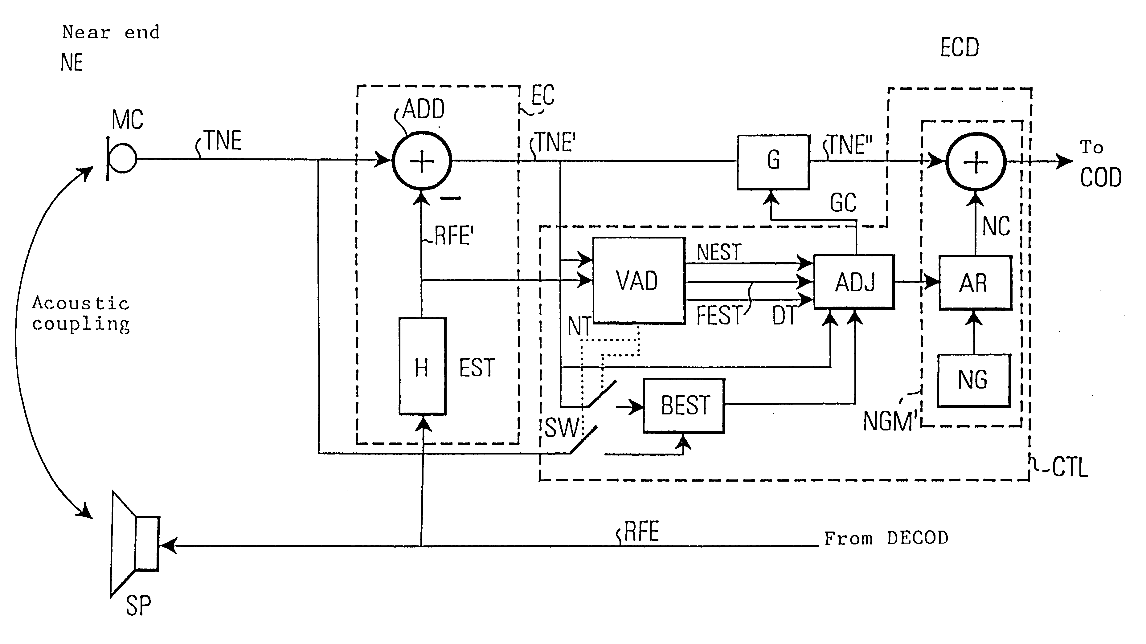
The second embodiment is also based on the general configuration as shown in FIG. 5. In the second embodiment the residual echo suppression device G comprises a residual echo filter G having an adjustable filter function g adapted to emphasize in the subtractor output signal TNE' of the subtractor ADD a background signal spectral content of the transmission signal in speech pauses. For this purpose the control means CNT contains a background signal model determining means which uses--as in the first embodiment--one or more of the signals TNE, TNE' for estimating a background signal model on the basis of one or more of these signals. When the background signal model has been determined, the background signal model determining means CNT sets the filter function g of the residual echo filter G in accordance with the determined background signal model such that the background signal spectral content is emphasized.

When the near end signal TNE is used for the determination...

third embodiment

OF THE INVENTION

Also a noise generation means NGM' similar to the one shown in FIG. 2B can be used in connection with the invention according to a third embodiment. In the third embodiment an additional noise generation means NGM can be provided essentially at the output of the echo cancellation device EC where an additional adder ADD2 is placed, cf. FIG. 5 and FIG. 5C.

That is, in the third embodiment illustrated in the block diagram of FIG. 5C, the adder ADD2 is used. However, by contrast to FIGS. 2B or 2C it should be noted that the injected noise process is not directly associated with the background noise process nor is the noise switched. The injected noise process is based on the background spectrum but- also weighted using TNE'. The weighting is used to mask the residual echo by a noise process. The masking threshold may be computed in a similar way to that of J. D. Jonston, "Transform coding of audio signals using perceptual noise criteria", IEEE Journal on selected areas in...


PUM


Abstract

An echo cancellation device (ECD) comprises an echo canceller (EC) including a transfer function estimator (EST, H) and a subtractor (ADD) and a residual echo suppression device (G, ADD2). The residual echo suppression device (G) comprises a residual echo filter (G) having an adjustable filter function (g). This filter function (g) can be adapted to either remove from the subtractor output (TNE') the spectral characteristics relating to the reception signal (RFE) and/or to emphasize in the subtractor output signal (TNE') a background signal spectral content relating to the transmission signal (TNE). A noise generation means (NGM') can be provided at the output of the adaptable filter (G) for injecting a noise process in to the filter output signal (TNE') prior to a speech coding in a speech coder (COD). The noise process masks in the filter output signal a spectral content relating to the reception signal (RFE).

Description

This application claims priority under 35 U.S.C. .sctn..sctn.119 and / or 365 to 199 35 808.7 filed in Germany on Jul. 29, 1999; the entire content of which is hereby incorporated by reference.The invention relates to an echo cancellation device for canceling echoes caused by a coupling of a reception signal received by a receiving unit of a transceiver unit of a telecommunication system to a transmitting unit of the transceiver unit. In particular, the invention eliminates echoes which are introduced in the transmitting path of the transceiver unit as a result of an acoustic coupling between a loudspeaker of the receiving unit to a microphone of the transmitting unit.More specifically, the echo cancellation device is intended to eliminate so-called residual echoes in the transmitting path which remain in the output of a conventional echo canceller after a main echo cancellation has been carried out.FIG. 1 shows in connection with FIG. 2A a block diagram of a conventional echo cancell...

Claims


Application Information

Patent Timeline
IPC IPC(8): H04B3/20H04B3/21H04M9/08G10L21/0224G10L21/0208H04B3/23H04B7/015H04M1/00H04M1/60
CPCH04B3/21H04M9/082
Inventor LINDGREN, ULFMISRA, MOHANPHILIPSSON, JOHN
Owner TELEFON AB LM ERICSSON (PUBL)
Why Eureka
Try Eureka