Workpiece support

a technology for supporting parts and supports, applied in the direction of support parts, metal-working holders, large fixed members, etc., can solve the problems of inaccuracy of machining, large storage requirements, and large capital outlay for each fixtur

Inactive Publication Date: 2003-07-29
BAE SYSTEMS PLC
View PDF13 Cites 33 Cited by
  • Summary
  • Abstract
  • Description
  • Claims
  • Application Information

AI Technical Summary

Problems solved by technology

This constitutes a considerable capital outlay for each of the fixtures and a considerable storage requirement.
This support only at spaced point regions may provide inadequate support during ma

Method used


Image

  • Workpiece support
  • Workpiece support
  • Workpiece support

Examples


Embodiment Construction

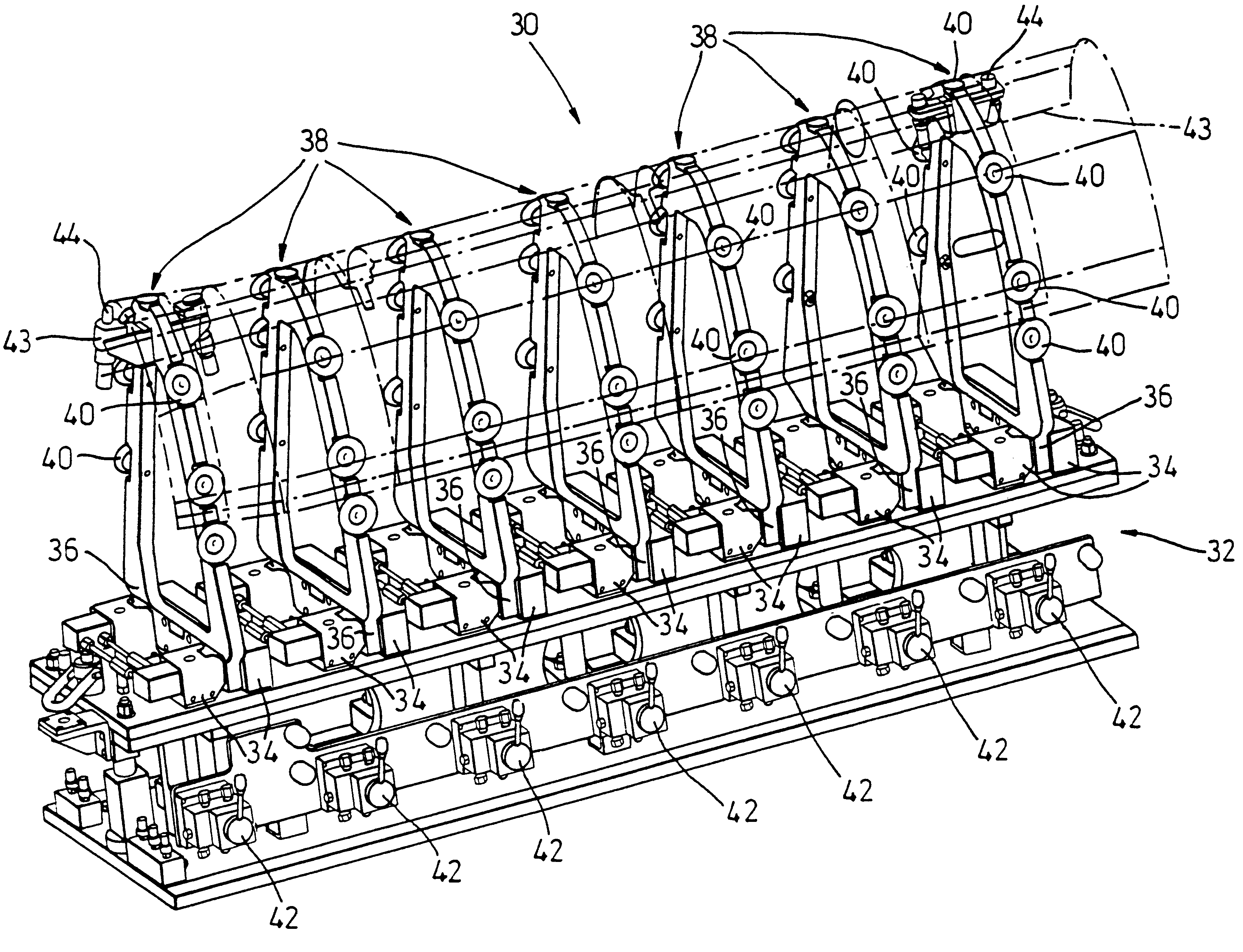
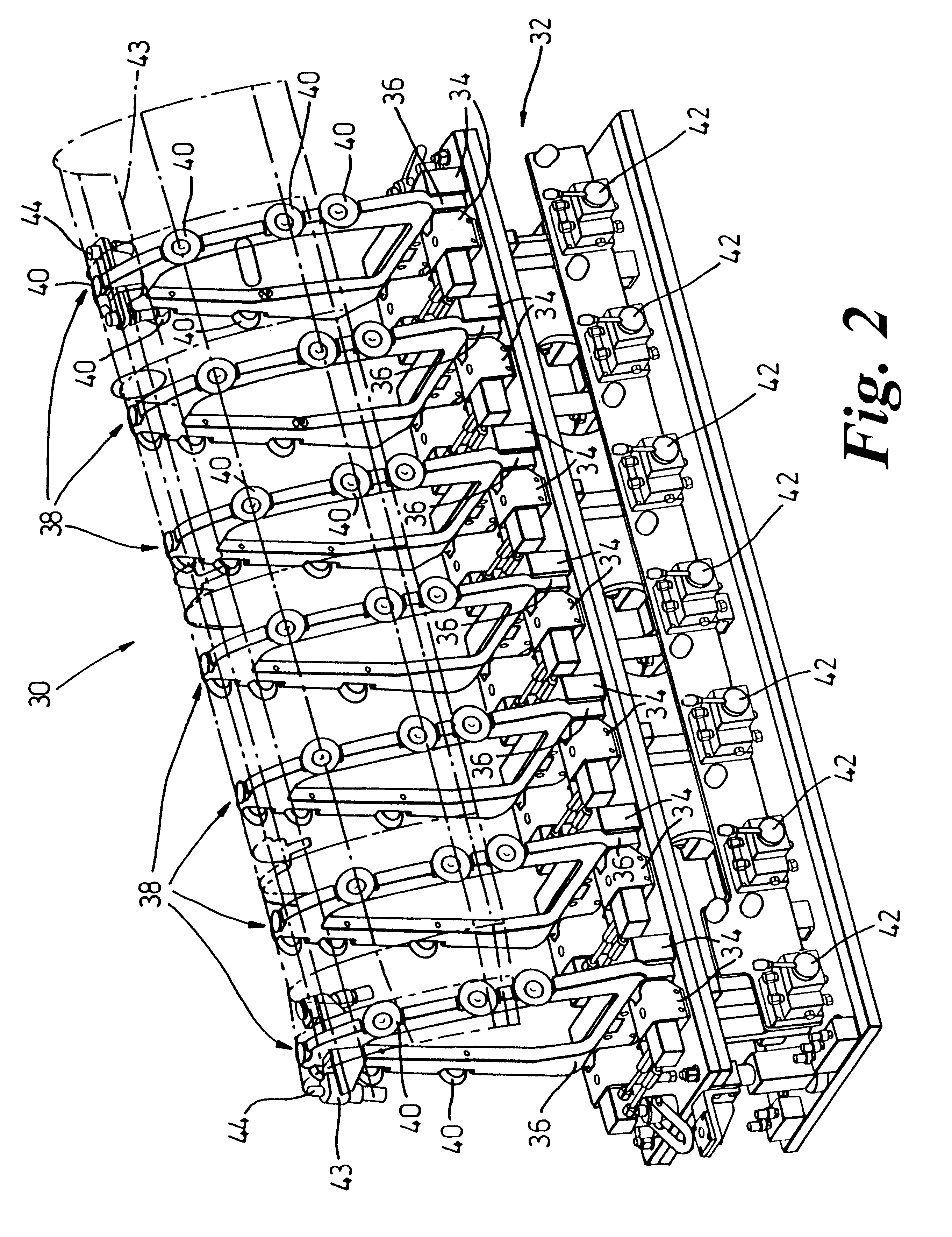
Referring to FIG. 2, the workpiece support 30 comprises a base 32 defining a number of stations, in this example seven. Each station comprises a hydraulically-operated clamp block 34 which is adapted to receive and clamp, the root 36 of a station frame element 38. The roots 36 are of a standard geometry which is reversible so that the frame element can be clamped in the clamp block 36 in either of two orientations. The remainder of the frame element is profiled in accordance with the profile of the workpiece to be supported. The system will include a library of different shaped frame elements for each of the workpieces to be supported, although some of the frame elements may be the same between different workpieces.

Each frame element includes, in this example, six suction cups 40; one at the apex of each frame element and three down each flank thereof. Suction is supplied to each of the cups 40 by suction tubes (not shown) which terminate in a standard connector (not shown) which co...


PUM

PropertyMeasurementUnit
Angleaaaaaaaaaa
Areaaaaaaaaaaa

Abstract

A modular workpiece support reconfigurable to support a number of similar, but different profiled workpieces (such as the leading edge skin sections of an aircraft wing) comprises a base 32 defining a number of stations along the component. Each station comprises a clamp block 34, and a frame element 38 of predetermined profile may be clamped in the clamp block in either of two different orientations (for hand and opposite). Each frame element includes a number of suction cups 40, the suction being controlled by a valve 42. The workpiece support may be rapidly reconfigured for a symmetric component simply by unclamping and rotating the frame element through 180°. The workpiece support may also be reconfigured for different profiles by selecting the appropriate frame elements from a library thereof.

Description

1. Field of the InventionThis invention relates to workpiece supports for supporting a workpiece and, in particular, but not exclusively, to a workpiece support for supporting a workpiece during a machining or routing operation.2. Discussion of Prior ArtThere are many applications where it is required to support one of a number of workpieces of different profiles during a machining or routing operation. For example, the leading edge skin of a typical commercial aircraft wing is made up of about a dozen sections of the same general shape but of different detailed profile. In an existing proposal, a sheet element is stretch-formed over a stretch-form of the required three-dimensional profile. After this initial forming the component is routed out of the stretch-formed skin. The stretch-forming and routing operations include six different stages as set out in FIGS. 1(a) to (f) of the accompanying drawings. Initially the margins 12 of the skin 10 are clamped in the jaws of a stretch for...

Claims


Application Information

Patent Timeline
IPC IPC(8): B25B11/00B25B5/00B23Q1/00B23Q1/03B64F5/00B23Q3/02B23Q3/08
CPCB23Q1/032B25B5/003B64F5/0036B25B11/005Y10T29/49622B64F5/50
Inventor HELM, STEPHEN P.HOGGATT, BRIAN A.MOORE, BRIAN
Owner BAE SYSTEMS PLC
Why Eureka
Try Eureka