Moving-picture compressing technique

a compression technique and picture technology, applied in the field of moving picture compression technique, can solve the problems of developing a time discrepancy, reducing the speed of receiving picture data, and delay in the time information at the receiver or playback apparatus

Inactive Publication Date: 2003-07-29
HTC CORP
View PDF14 Cites 37 Cited by
  • Summary
  • Abstract
  • Description
  • Claims
  • Application Information

AI Technical Summary

Problems solved by technology

However, when the frame rate which is predetermined is changed due to a loss of some of the frames to be received by dropping or any other reason, not by intentional decimation of the frames such as schemed with the first or third prior arts, if it is used without correction in the compression encoding, then there will be developed a time discrepancy such as a delay in the time information at the receiver or playback apparatus.
The drawback like this may appear in such a moving picture compressing apparatus as composed of a software architecture when a series of moving pictures are continuously received in real time from a source such as a video camera and subjected in a succession to the compression encoding.
The low processing speed of a CPU (central processing unit) or a heavy load on the CPU due to multitask processing in parallel causes the speed of receiving the picture data to be decreased or prevents the picture data from being received at a constant speed.
The second prior art also has no scheme for

Method used


Image

  • Moving-picture compressing technique
  • Moving-picture compressing technique
  • Moving-picture compressing technique

Examples


first embodiment

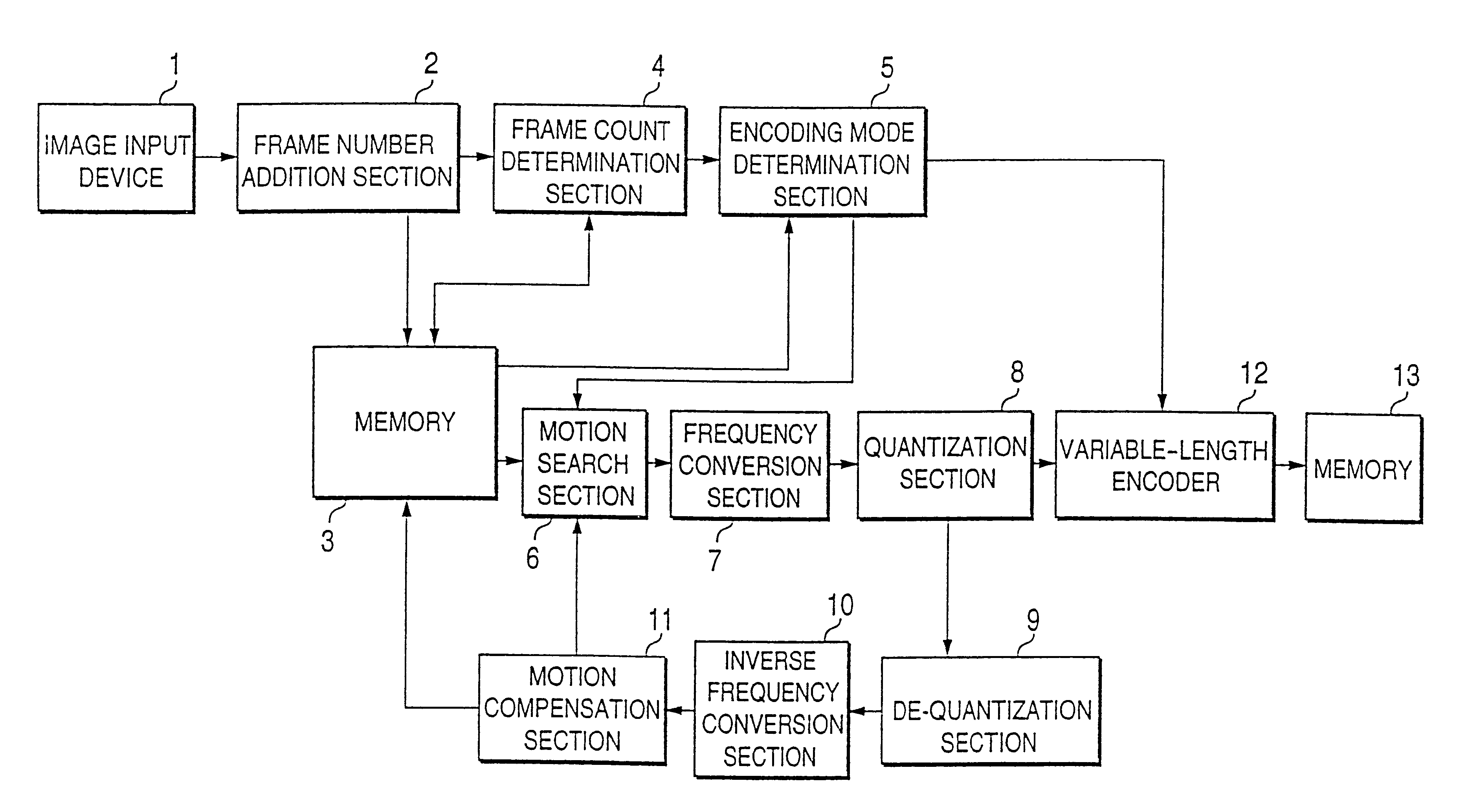
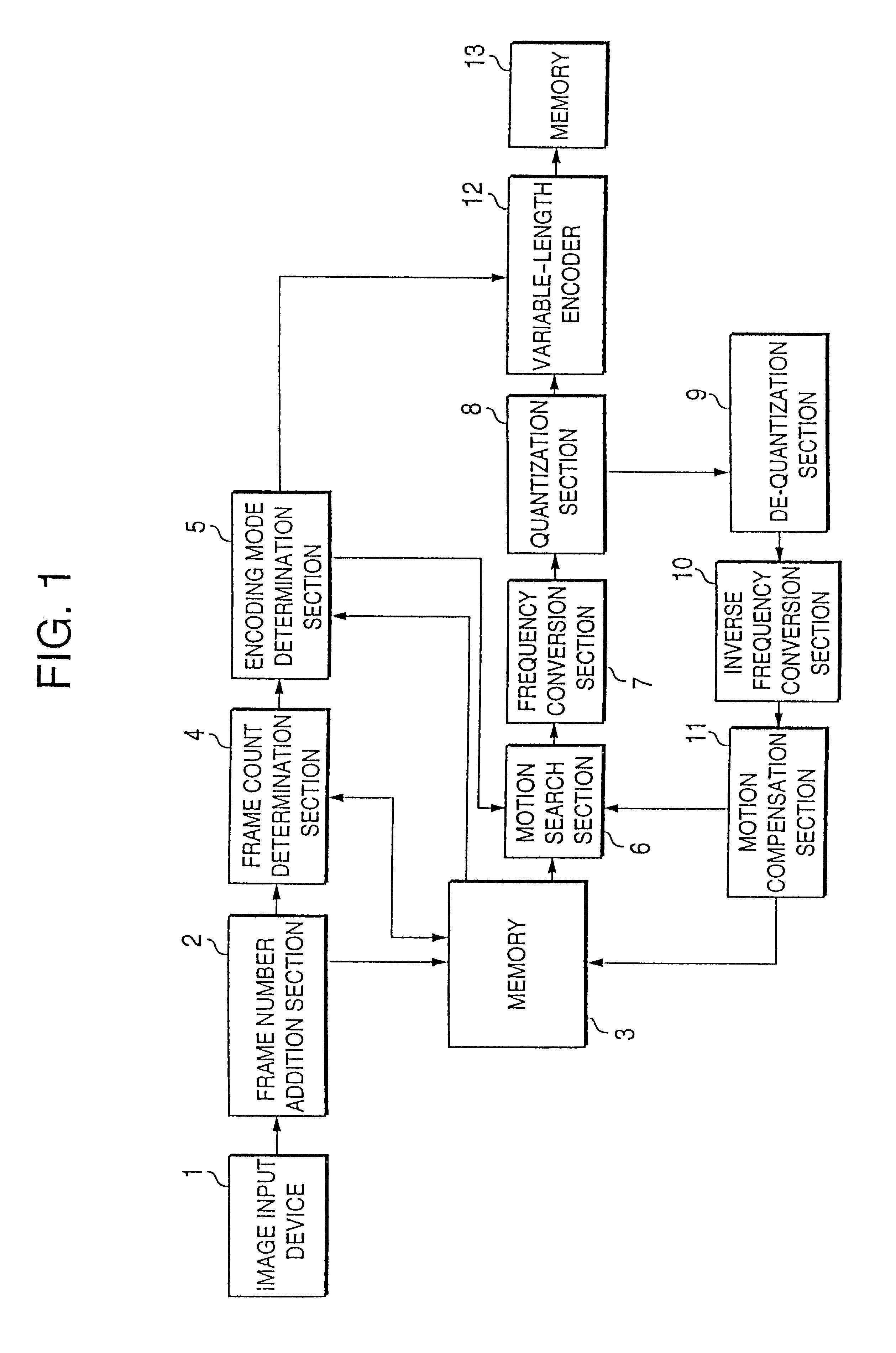
FIG. 1 is a block diagram of an electrical arrangement of a moving picture compressing apparatus according to the present invention.

The moving picture compressing apparatus includes image input device 1, frame number addition section 2, memory 3, frame count determination section 4, encoding mode determination section 5, motion search section 6, frequency conversion section 7, quantization section 8, de-quantization section 9, inverse frequency conversion section 10, a motion compensation section 11, variable-length encoder 12, and memory 13.

The image input device 1 includes an analog-to-digital (A / D) converter and receives frame by frame an analog video signal from a signal source such as a video camera (not shown) and converts the received analog video signal to a digital signal composed of frames of data FD. The signal source supplies a succession of moving pictures in real time.

The frame number addition section 2 includes time information acquiring means, such as a timer, for ac...

second embodiment

FIG. 8 is a block diagram showing an electrical arrangement of a moving picture compressing apparatus according to the second embodiment of the present invention. As shown in FIG. 8, like components as those shown in FIG. 1 are denoted by the same numerals and will be explained in no more detail. The moving picture compressing apparatus of the second embodiment includes a GOP structure modification section 21 disposed between the image input device 1 and the frame number addition section 2.

The GOP structure modification section 21 has a GOP structure table 22 therein as shown in FIG. 9. When the present frame of data FD.sub.F received from the image input device 1 is the frame of data FD.sub.T at the head of the group of pictures GOP, the structure of the group of pictures GOP is modified, with reference to the GOP structure table 22, by comparing between the frame rate designated to the moving picture compressing apparatus and an actual frame rate given from the absolute or relativ...


PUM


Abstract

A compression-encoding method allowing any discrepancy such as a delay caused by a change in frame rate to be avoided is disclosed. It is determined whether a predetermined number of frames required for forming a GOP have been inputted and, when the predetermined number of frames have not been all supplied, a dropped frame is compensated for by interpolation of a proceeding frame previous to the dropped frame to produce an interpolated group of pictures. Each frame of the interpolated GOP is compression-encoded to produce encoded moving picture data to be stored into a memory.

Description

1. Field of the InventionThe present invention relates to a moving picture compression technique, and particularly to a method and apparatus for compression-encoding a moving picture supplied in real time after dividing it in units of a plurality of frames.2. Description of the Related ArtThere have been proposed several conventional moving picture compressing apparatuses for compression-encoding a moving picture supplied in real time as disclosed, for example, in Japanese Patent Application Laid-open No. 7-177514, No. 8-307878, No. 8-336138, and No. 10-136380. The details of these publications will be described.A moving picture compressing apparatus disclosed in the above Publication No. 7-177514 is arranged such that frame decimation is performed during compression encoding of a moving picture and the compression-encoded data is transmitted to a receiver. At the receiver, the compression-encoded data is decoded and expanded to reproduce the original moving picture by interpolating...

Claims


Application Information

Patent Timeline
IPC IPC(8): G06T9/00H04N7/50H04N7/46H04N7/26H04N19/50H04N19/114H04N19/132H04N19/142H04N19/159H04N19/177H04N19/46H04N19/463H04N19/503H04N19/587H04N19/61H04N19/625H04N19/70H04N19/91
CPCH04N19/61H04N19/114H04N19/132H04N19/177H04N19/587
Inventor ISHIKAWA, HIROYUKI
Owner HTC CORP
Why Eureka
Try Eureka