Dimming ballast for compact fluorescent lamps

a compact fluorescent lamp and ballast technology, applied in the direction of instruments, light sources, electrical equipment, etc., can solve the problems of insufficient bus voltage for the ballast to be able to operate, and the ballast cannot operate over the complete range of adjustment of the dimmer

Inactive Publication Date: 2003-08-05
INFINEON TECH AMERICAS CORP
View PDF6 Cites 41 Cited by
  • Summary
  • Abstract
  • Description
  • Claims
  • Application Information

AI Technical Summary

Benefits of technology

It should be noted that if the dimmer is set too low, the triac will never fire when a capacitive load is connected. Also when the ballast is running and the dimmer is turned too low, there will be insufficient bus voltage for the ballast to be able to operate. Because of these factors it is impossible for the ballast to operate over the complete range of adjustment of the dimmer. There will also be some hysteresis so that when the ballast is being dimmed down and reaches the point where the lamp goes out, the dimmer has to be turned back up some way before the lamp will strike again.

Problems solved by technology

Also when the ballast is running and the dimmer is turned too low, there will be insufficient bus voltage for the ballast to be able to operate.
Because of these factors it is impossible for the ballast to operate over the complete range of adjustment of the dimmer.
There will also be some hysteresis so that when the ballast is being dimmed down and reaches the point where the lamp goes out, the dimmer has to be turned back up some way before the lamp will strike again.

Method used


Image

  • Dimming ballast for compact fluorescent lamps
  • Dimming ballast for compact fluorescent lamps
  • Dimming ballast for compact fluorescent lamps

Examples


Embodiment Construction

Functional Description

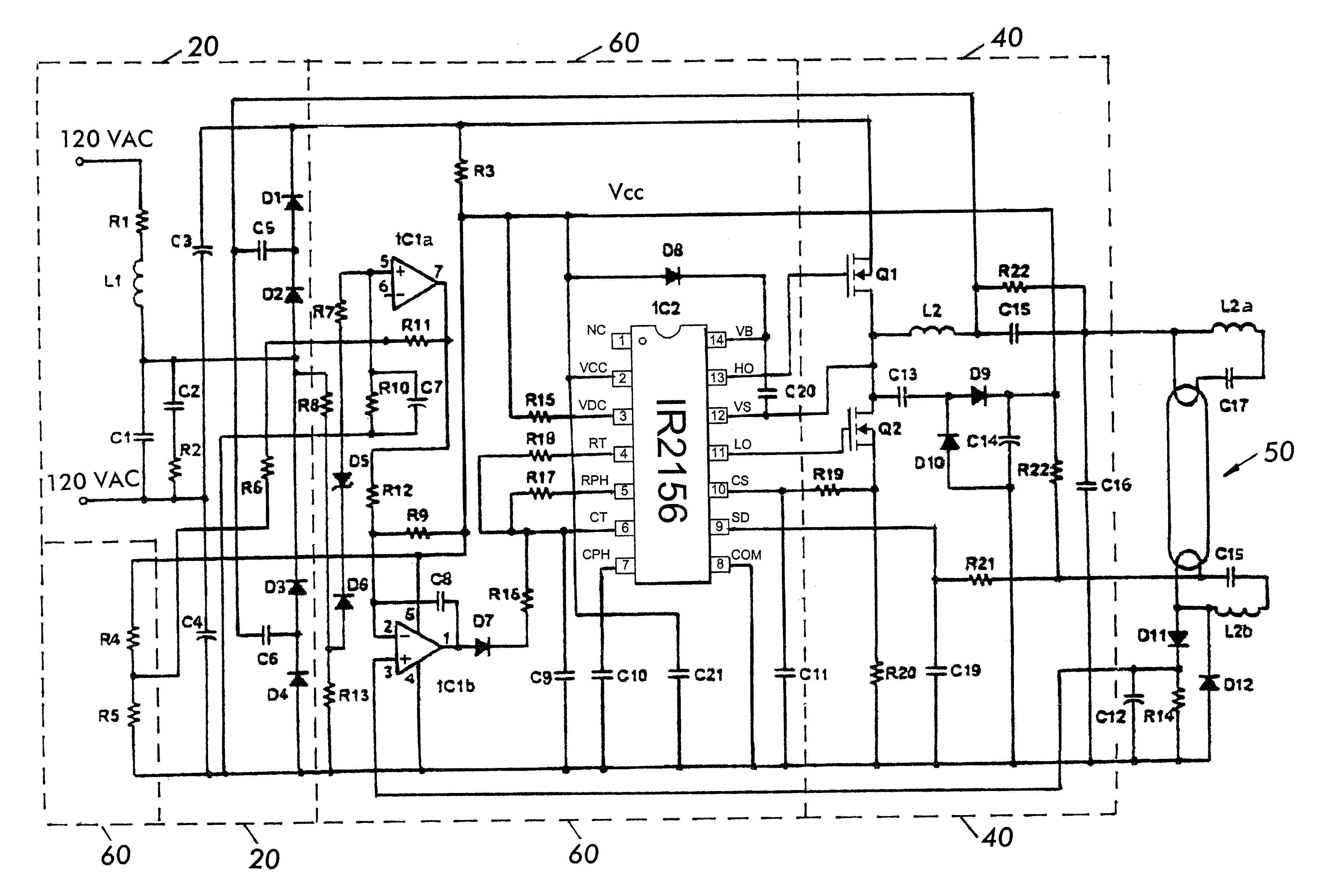
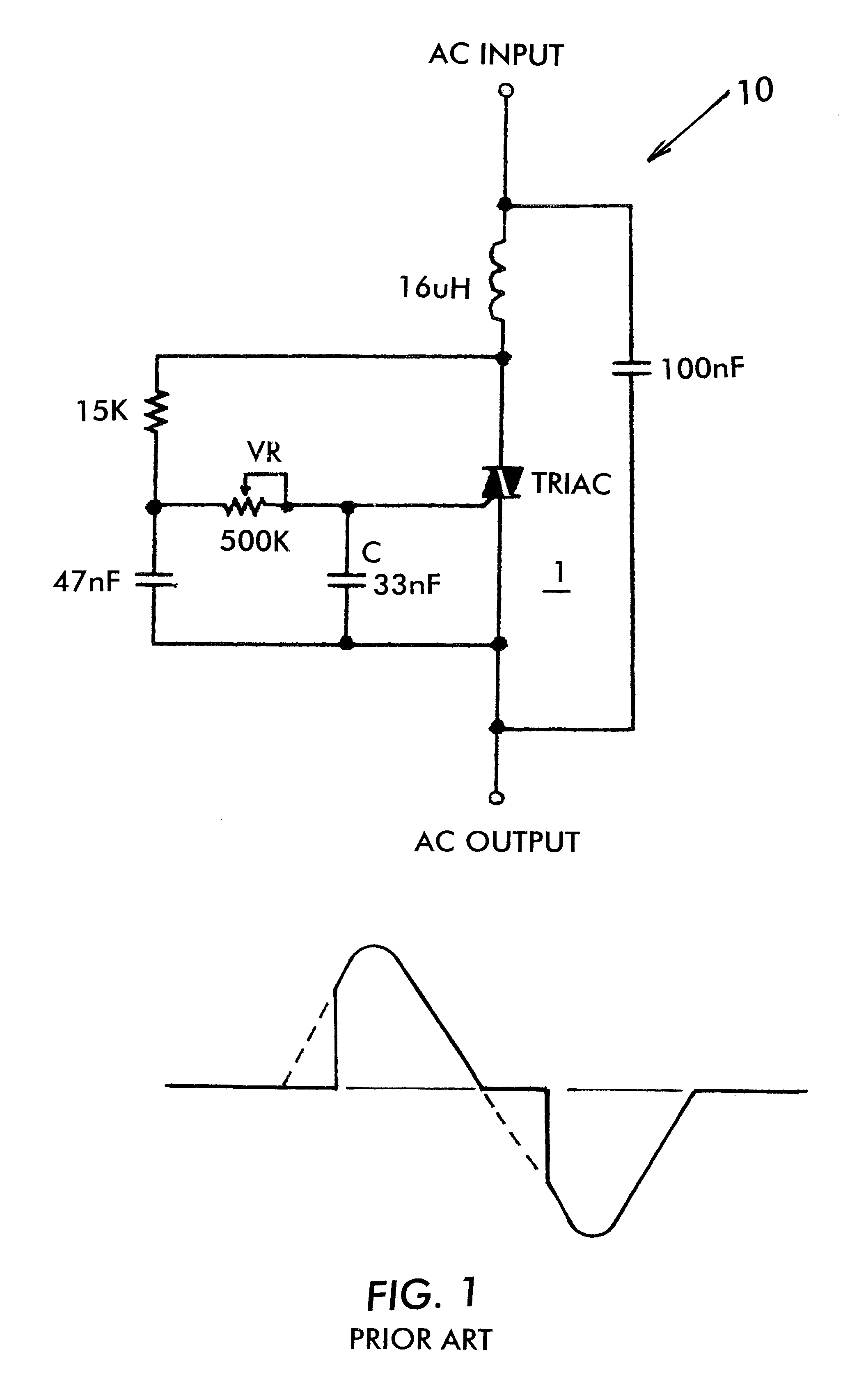
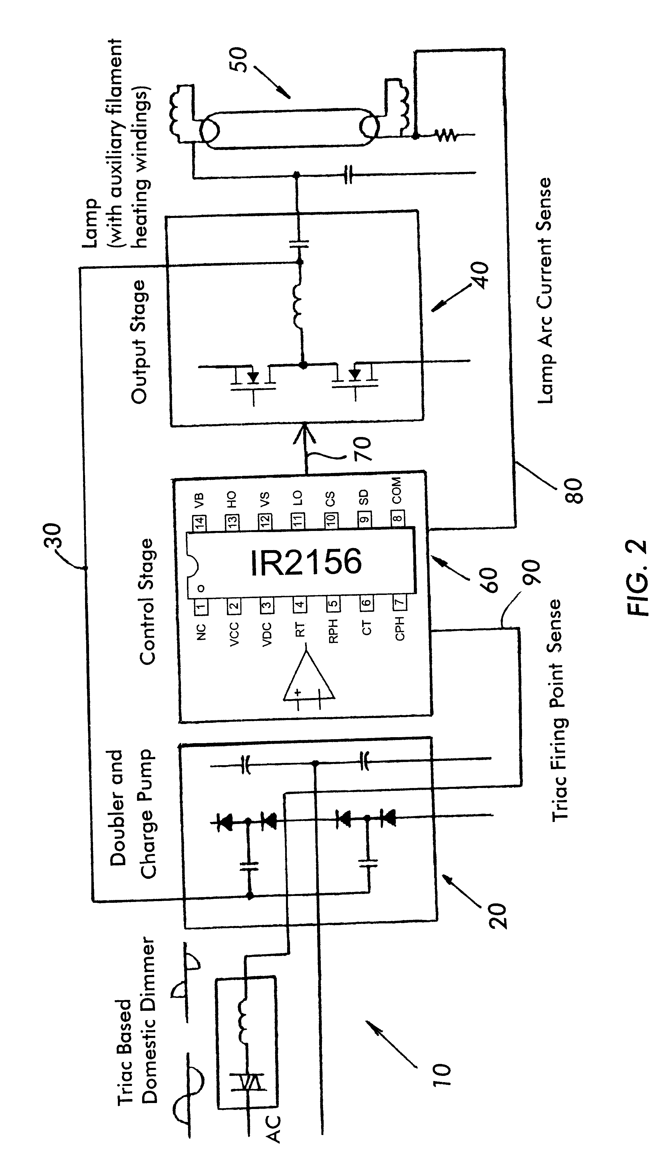
With reference now to the drawings, FIG. 2 shows the basic block diagram of a phase cut dimmable ballast according to the present invention. The ballast includes a phase cut dimmer 10 which can be constructed as shown in FIG. 1, and which is coupled to the AC mains. The output of the dimmer 10 is provided to a voltage doubler and charge pump 20. As shown, the hot side from the AC mains is coupled through the dimmer 10 and the neutral is provided directly into the doubler and charge pump 20. One output of the doubler and charge pump, not shown in FIG. 2, is a DC bus voltage provided to an output stage 40 comprising a half bridge transistor circuit, preferably implemented using FETs. This DC bus voltage is switched by the output stage to power the lamp. An input 30 is provided from the output stage 40 to control the operation of the doubler and charge pump 20. The DC bus voltage is also reduced to provide low voltage power to a control stage 60. The output of the...


PUM


Abstract

A fluorescent lamp ballast circuit including a phase cut dimmer connectable to a source of AC power, the selectable phase cut dimmer and an electronic switch having a trigger voltage and a conduction period, when the electronic switch triggers to the end of the half cycle, a rectifying and charging circuit coupled to the output of the phase cut dimmer for providing a DC voltage across a DC bus, a filter circuit receiving the output of said phase cut dimmer and converting the output to a control signal related to the firing angle of the electronic switch; an output stage coupled to the lamp, the output stage having at least one electronic switching device; the ballast control circuit including a control input for changing a frequency of said pulsed power signal, the control input being coupled to said control signal, the control signal varying in accordance with the firing angle of he electronic switch, thereby varying the brightness level of said fluorescent lamp.

Description

BACKGROUND OF THE INVENTIONIt has often been a disadvantage with fluorescent lamp electronic ballasts that they have been unable to be dimmed with a standard (phase cut) type of dimmer, particularly in the case of small integral ballast-lamp combinations commonly used in the home to save energy. This is due to the fact that, where there is no power factor correction, the ballast circuit input consists of a rectification stage followed by a large storage capacitor connected to the AC mains supply that provides the DC bus from which the high frequency half bridge and output section is supplied. In such a system, current is drawn from the mains only near the peak of the mains voltage where the storage capacitor charges and not during the remainder of the mains half-cycle.Virtually all domestic and professional dimming systems are based on triacs. These devices will conduct once they have been fired, only while current flows in excess of the holding current of the deice. These dimmers w...

Claims


Application Information

Patent Timeline
Patent Type & Authority Patents(United States)
IPC IPC(8): H05B41/39H05B41/295H05B41/285H05B41/28H05B41/392
CPCH05B41/2855H05B41/295H05B41/3924H05B41/3925H05B45/355
Inventor RIBARICH, THOMAS J.GREEN, PETER
Owner INFINEON TECH AMERICAS CORP
Why Eureka
Try Eureka