Solid cryogen cooling system for focal plane arrays

a cryogenic cooling and focal plane array technology, applied in the field of cryogenic cooling systems for cooling focal plane arrays, can solve the problems of increasing the demands placed on the cooling system, bulky components and additional support hardware, and affecting the uniformity of the fpa,

Inactive Publication Date: 2003-08-12
RAYTHEON CO
View PDF4 Cites 8 Cited by
  • Summary
  • Abstract
  • Description
  • Claims
  • Application Information

AI Technical Summary

Problems solved by technology

Any spatial or temporal variations in temperature across the FPA may cause prohibitive FPA nonuniformities.
The bulky components and additional support hardware may require additional cooling, which increases demands placed on the cooling system.
The bulky support structure, conventionally thought to improve temperature stability, may conduct excess heat from the warm missile body into the FPA, thereby reducing system cooling efficiency.
Furthermore, the additional bulky mechanical FPA support hardware may cause alignment problems with the on board optical or infrared system during installation and operation, thereby increasing installation and operating costs.
In addition, missile maneuvering may cause the cooling liquid...

Method used


Image

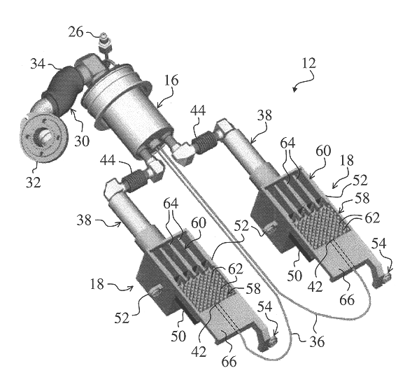
  • Solid cryogen cooling system for focal plane arrays
  • Solid cryogen cooling system for focal plane arrays
  • Solid cryogen cooling system for focal plane arrays

Examples


Embodiment Construction

While the present invention is described herein with reference to illustrative embodiments for particular applications, it should be understood that the invention is not limited thereto. Those having ordinary skill in the art and access to the teachings provided herein will recognize additional modifications, applications, and embodiments within the scope thereof and additional fields in which the present invention would be of significant utility.

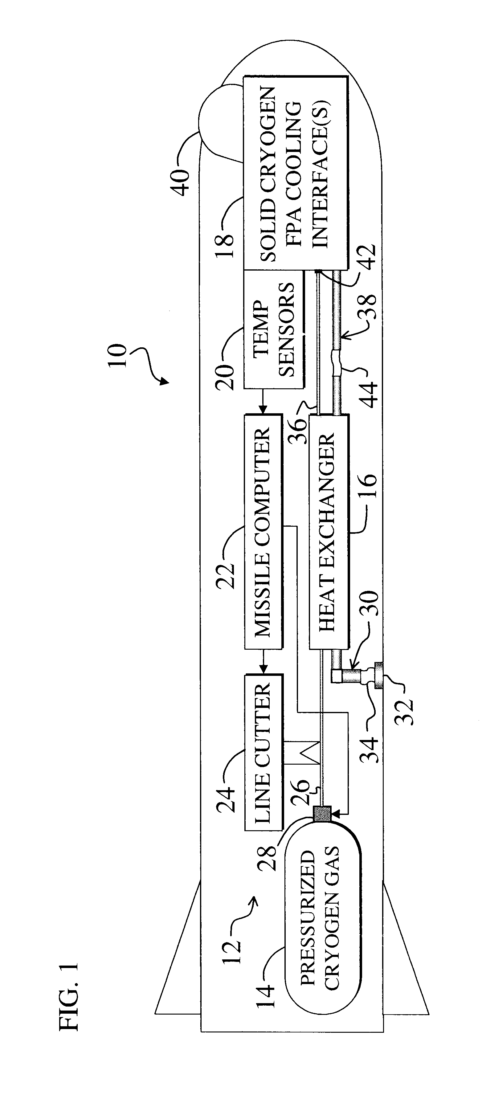
FIG. 1 is a diagram of a missile system 10 employing a solid cryogen infrared Focal Plane Array (FPA) cooling system 12 constructed in accordance with the teachings of the present invention. For clarity, various well-known components, such as power supplies, actuators, heat exchanging coils, explosives compartments, and so on, have been omitted from the figures. However, those skilled in the art with access to the present teachings will know which components to implement and how to implement them to meet the needs of a given application.

The...


PUM


Abstract

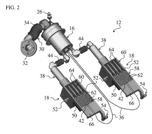
A cryogenic cooling system (12) for cooling electromagnetic energy detectors (50). The cooling system (12) includes a first mechanism (18) that accommodates cryogen fluid in one or more spaces (58, 60). A second mechanism (16, 42) freezes the cryogen fluid in the one or more spaces (58, 60) adjacent to the electromagnetic energy detectors (50). In a specific embodiment, the electromagnetic energy detectors (50) comprise an infrared focal plane array (50). The second mechanism (16, 42) includes a heat exchanger (16) that is mounted separately from the first mechanism (18). The one or more spaces (58, 60) are fitted with three-dimensional cooling interface surfaces (62, 64). The three-dimensional cooling surfaces (62, 64) are implemented via a thermally conductive matrix (62, 64). The thermally conductive matrix (62, 64) is a copper metal matrix or carbon/graphite matrix, and the solid cryogen reservoir (18) is a beryllium reservoir (18). The solid cryogen reservoir (18) includes integrated mounting features (52, 54) for mounting the reservoir (18) to a missile housing and a surface for attaching the focal plane array (50) to the reservoir (18). The second mechanism (16, 42) includes a Joule-Thomson orifice (42) that employs the Joule-Thomson effect to cool the cryogen fluid to a solid state. The first mechanism (18) includes a selectively detachable cryogen canister that provides pressurized cryogen fluid to the heat exchanger (16). The heat exchanger (16) directs cooled pressurized cryogen fluid to the solid cryogen reservoir (18) and Joule-Thomson orifice (42) and is positioned remotely from the cryogen reservoir (18). In an illustrative embodiment, the heat exchanger (16) outputs cooled cryogen gas to plural solid cryogen reservoirs (18) to cool plural corresponding infrared focal plane arrays (50). A line cutter selectively detaches the gas canister and/or the heat exchanger (16) from the missile in response control signal from a computer. The computer generates the control signal after a predetermined amount of the cryogen fluid is present in the cryogen reservoir (18) or after a predetermined time interval.

Description

1. Field of InventionThis invention relates to cooling systems. Specifically, the present invention relates to cryogenic cooling systems for cooling focal plane arrays.2. Description of the Related ArtCryogenic cooling systems are employed in various demanding applications including military and civilian active and remote sensing, superconducting, and general electronics cooling. Such applications often demand efficient, reliable, and cost-effective cooling systems that can achieve extremely cold temperatures below 80 degrees Kelvin.Efficient cryogenic cooling systems are particularly important in sensing applications involving high-sensitivity infrared focal plane arrays of electromagnetic energy detectors (FPA's). An FPA may detect electromagnetic energy radiated or reflected from a scene and convert the detected electromagnetic energy into electrical signals corresponding to an image of the scene. To optimize FPA imaging performance, any FPA detector nonuniformities, such as diff...

Claims


Application Information

Patent Timeline
IPC IPC(8): G01S3/781G01S3/78
CPCG01S3/781
Inventor PFLIBSEN, KENT P
Owner RAYTHEON CO
Why Eureka
Try Eureka