Filler element for a tank

a technology for filling elements and tanks, applied in the direction of transportation and packaging, manufacturing tools, container discharging methods, etc., can solve the problems of reducing the effectiveness of filling mass, reducing the available open interior space, and not entirely successful designs

Inactive Publication Date: 2003-08-12
FENTON RONALD L
View PDF19 Cites 24 Cited by
  • Summary
  • Abstract
  • Description
  • Claims
  • Application Information

AI Technical Summary

Benefits of technology

It is a further objective to present such a design for a filler element which can be easily formed into a variety of shapes with minimal crushing to preserve the effectiveness of the filler mass.
To eliminate nesting of the mesh within the filler element, various sections of the mesh corresponding to the folds are arranged to present openings of varying sizes, such that, when folded, sections of differing sized openings are juxtaposed.

Problems solved by technology

These designs have not been entirely successful for a variety of reasons; but most importantly, because they all exhibit free edges which break off during use and then clog fuel lines (typically referred to as "flaking").
Moreover, the final crushing step compacts this filler element, reducing the available open interior space and thereby reducing its effectiveness as a filler mass.
By using holes of irregular size in the mesh, nesting of the mesh layers is reduced, but the problem of "flaking" from exposed edges is not resolved.
This element is used to retro-fit tanks with a filler mass by inserting the element through the tank opening; but the extensive number of free edges radiating from the supporting member in this design increases the "flaking" problem many fold, thereby preventing its use in any application where a clogged fuel line would pose an unacceptable risk.

Method used


Image

  • Filler element for a tank
  • Filler element for a tank
  • Filler element for a tank

Examples


Embodiment Construction

)

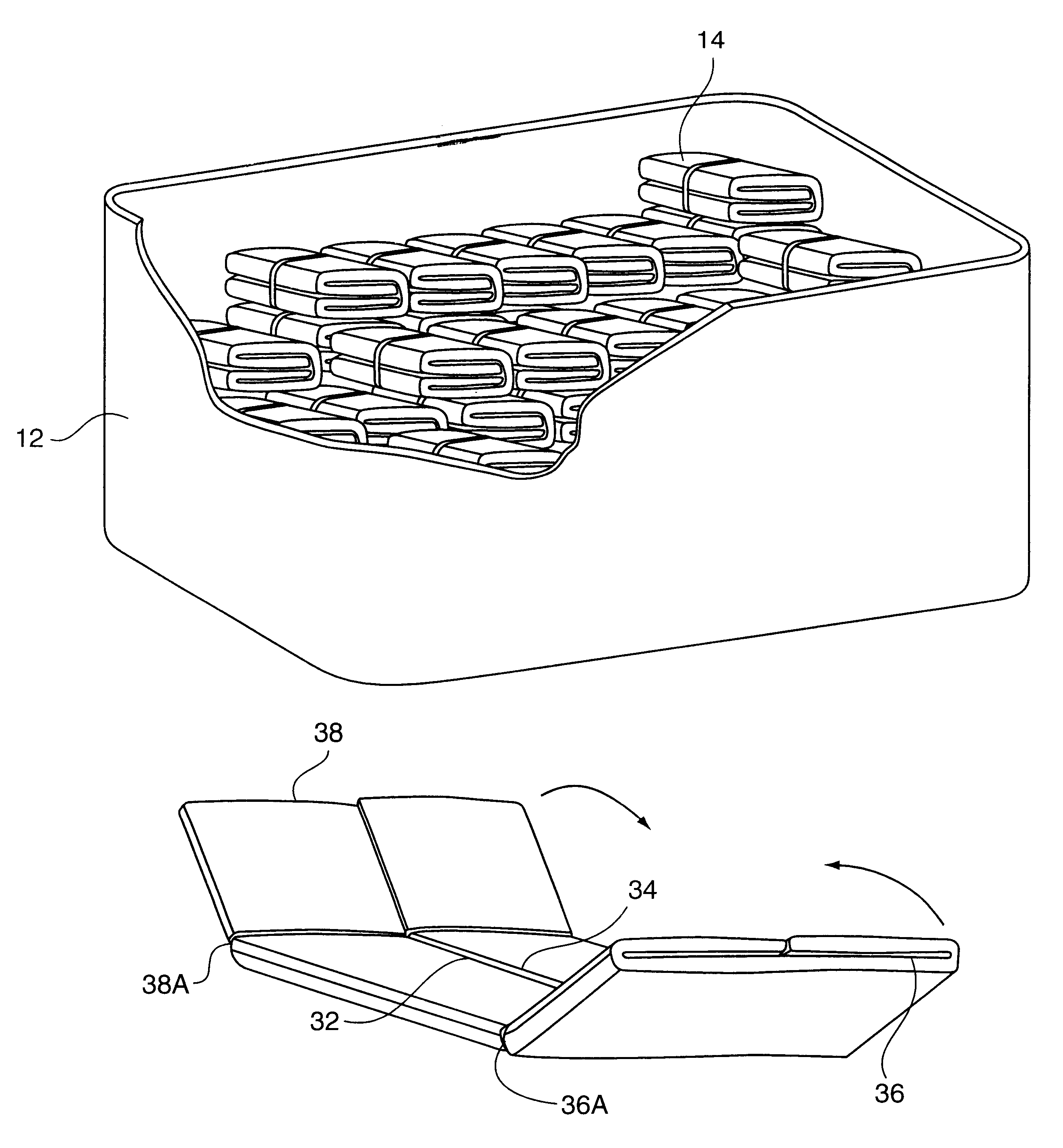
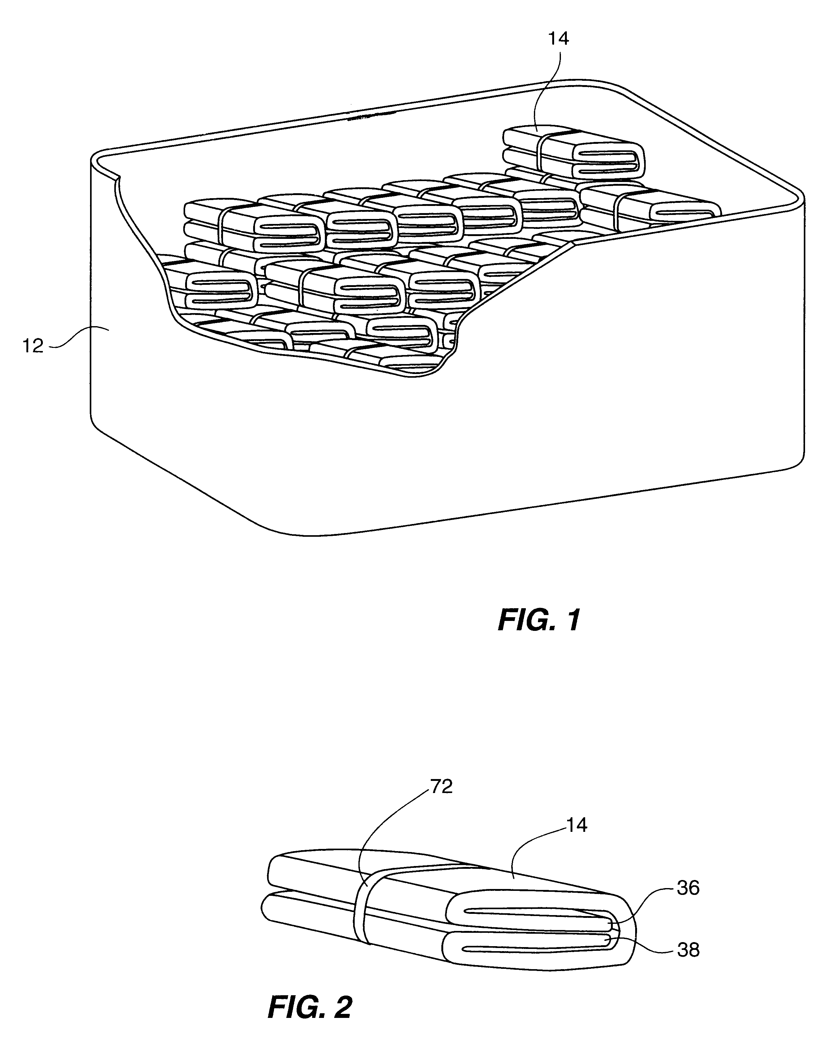
Turning first to FIG. 1, there is illustrated a tank 12 having a plurality of fuel permeable filler mass insert elements 14 stacked therein to form a thermal filler mass within the tank. While only a portion of the tank is shown here for clarity, in practice an entire closed tank with an access opening is used, as is well known in the art. Also, the entire tank is filled with the filler elements, such that they are in thermal contact with one another and with the tank walls. During manufacture of the tank, the insert elements may be stacked inside before the tank is closed, or alternatively, the filler elements may be manufactured in a size small enough to be inserted through an access opening of the tank after the tank is completed.

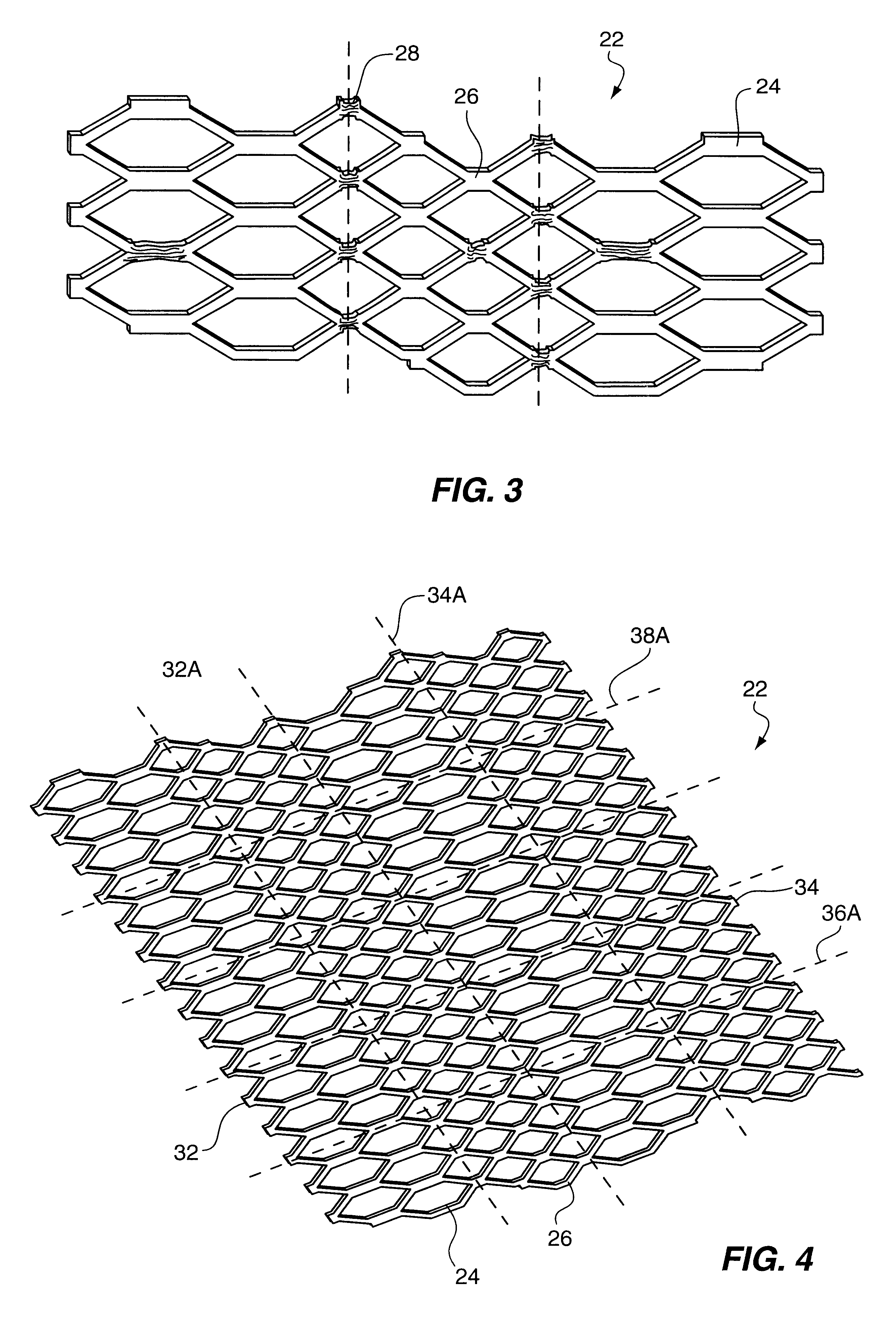
A filler element constructed in accordance with the teachings of the present invention, such as is depicted in FIGS. 2, 9 and 10, is formed from at least one sheet of expanded metallic foil mesh (see FIGS. 3 and 4), having longitudinal sections of large...


PUM

PropertyMeasurementUnit
thermalaaaaaaaaaa
massaaaaaaaaaa
shapeaaaaaaaaaa

Abstract

Filler elements for a tank of combustible fluid described herein are formed from a sheet of foil mesh material by a multiple fold technique. The folding process places the free edges of the sheet in the center of the filler element where they are protected and where any piece that breaks off will be trapped. The sides are first folded inwardly and then the ends are folded inwardly. Finally, this intermediate member is rolled, formed, molded or folded further into the final desired shape for the filler element. Folding is facilitated by use of a crushed crease along desired fold lines. To reduce nesting of the mesh, various sections of the mesh corresponding to the fold lines present openings of differing sizes.

Description

1. Field of the InventionThe present invention relates generally to receptacles for combustible materials, such as fuel tanks. More particularly, this invention relates to an improvement in the filler mass inserted in such tanks to prevent explosion. Specifically, this invention relates to the design of discreet filler elements which are used to fill a tank and which have folded in portions to prevent flaking of exposed end edges of layers of metal foil sheet material from which the filler mass is formed.2. Description of the Prior ArtIt is well known in the prior art that a filler mass insert for a tank may be formed from a metal foil mesh and will act to prevent explosion by transmitting heat from hot spots occurring on the tank exterior. This filler mass is traditionally formed of multiple layers of an expanded metal foil (U.S. Pat. No. 3,356,256), the method of manufacture thereof being well established in the art (U.S. Pat. No. 4,921,118). The resulting multi-layer mass can be ...

Claims


Application Information

Patent Timeline
Patent Type & Authority Patents(United States)
IPC IPC(8): A62C3/00A62C3/06B60K15/03B64D37/32B65D90/22B64D37/00F17C13/00F17C13/12
CPCA62C3/06B60K15/03B60K15/03006B64D37/32B65D90/22F17C13/123B60K2015/03381Y10T29/49826F17C2201/06B60K2015/03467
Inventor FENTON, RONALD L.
Owner FENTON RONALD L
Why Eureka
Try Eureka