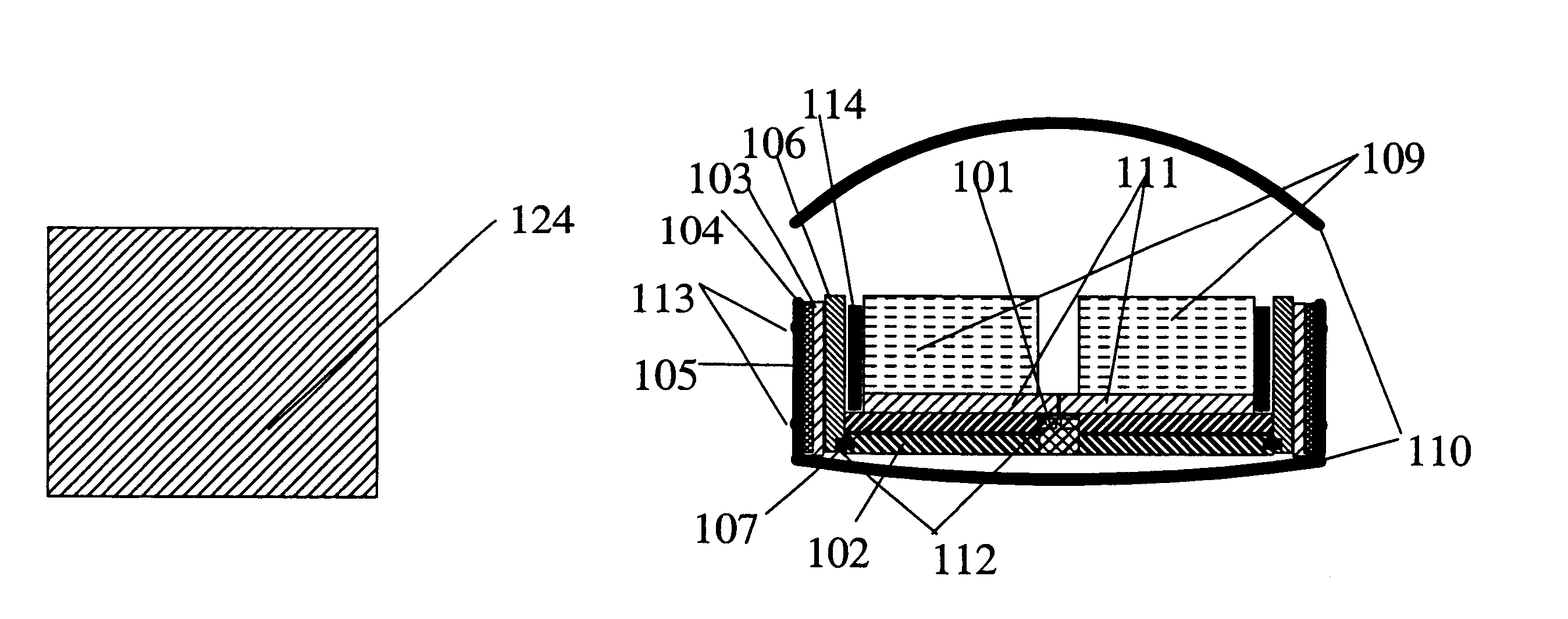
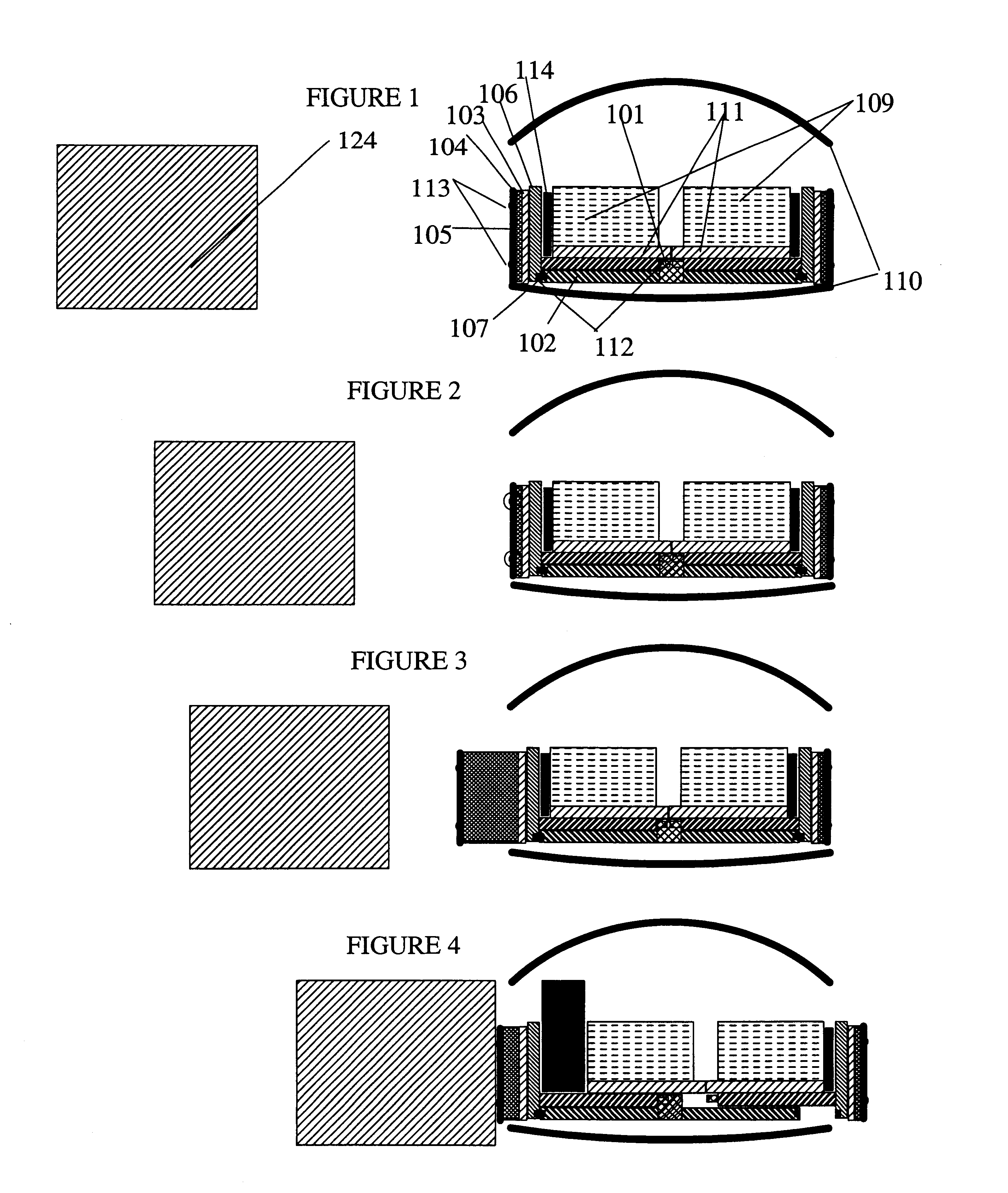
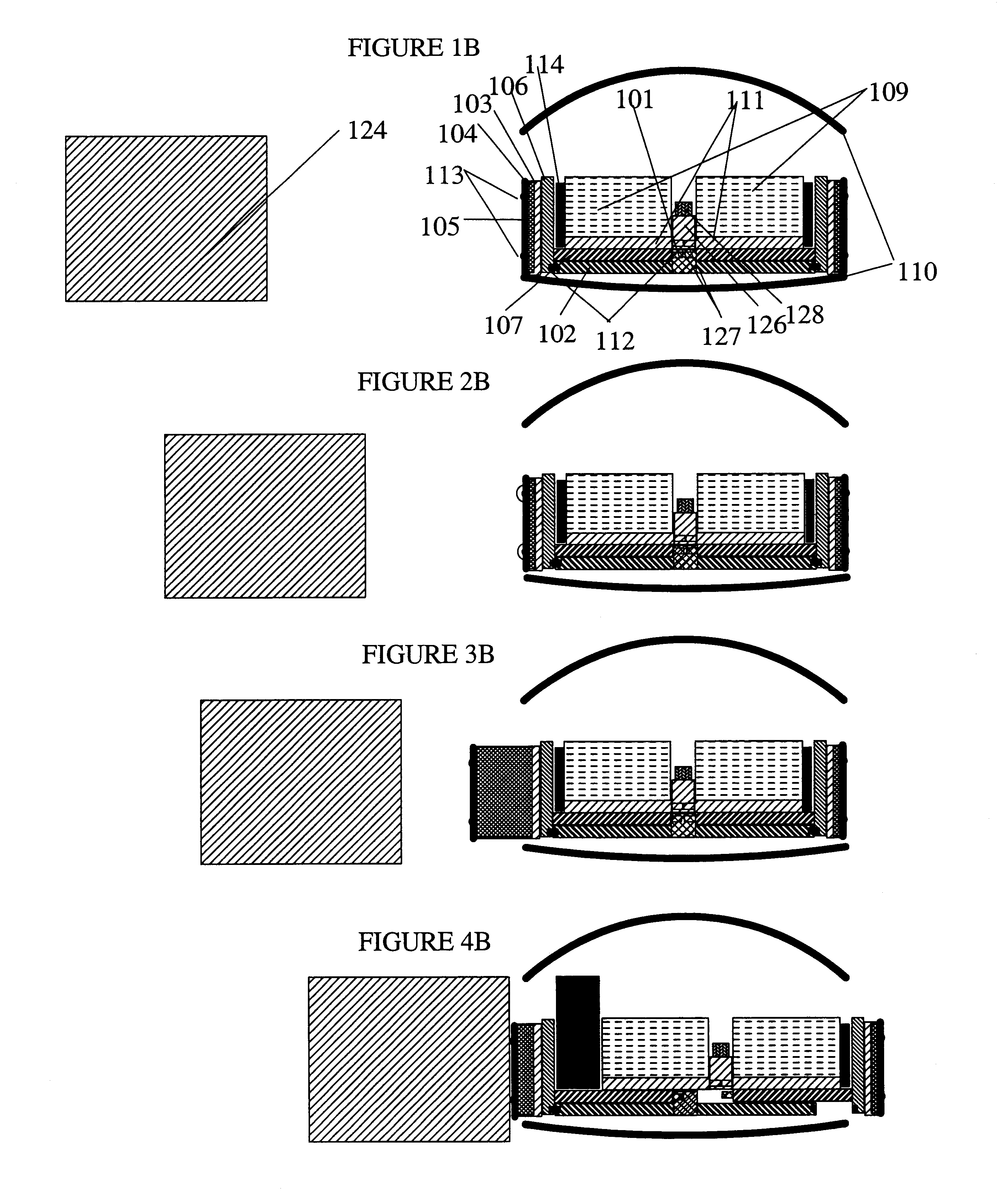
However such fixed shell structures have had limited success in protecting passengers and drivers when there are lateral collisions as passengers undergo the same impact related accelerations and decelerations as the remaining parts of the vehicle, as space limitations don't allow for "crumple zones" as in the case of impact protection for head on collisions.
Passengers are particularly vulnerable to side impacts as they cannot take preemptive measures as with head-on collisions where there is speed control and directional control that is available.
As vehicle speeds have increased substantially in the last several decades, these safety considerations for passengers have become critical and urgent.
However, there are limits within the rigid shell paradigm for two reasons: First, the energy of impact cannot be easily diverted away from passengers into the remaining mass of the vehicle on impact.
Second, the rigid shell needs to support high shear stresses on lateral impact and related compressive loads to the passenger compartment of the vehicle a factor that can only be addressed with greater mass of the vehicle that will impact its performance.
Moreover, none of this Background art even addresses the issue of
energy transfer away from the passengers to the mass of the vehicle on impact and concurrently provide a mechanism for easy access to the vehicle with ejector seats.
Moreover, it cannot be used in a front seat even for its limited functionality with
doors fixed to the seat as driving
instrumentation (
steering wheel etc) will not allow a door to slide through the compartment.
Finally it does not provide any comfort features for passengers over and above a bench seat.
Solomon U.S. Pat. No. 2,758,872 (1953) provides a sliding bench seat that goes through the doorway and for the same reasons as Sloan does not provide protection in side impacts or provide any comfort features over and above a bench seat.
Moreover, none of them provide utility for mounting and dismounting a vehicle except for a bench seat that slides out on either side of the vehicle, or provide comfort features except for seating arrangement on a bench seat and in one of the above--the
lateral movement for convenience of the operator.
None of these items of background art provide mechanisms to transfer energy away from passengers in lateral impacts, or provide other safety arrangements or provide utility for mounting and dismounting the vehicle or provide comfort features for passengers in the operating position.
Such devices cannot be implemented on the side of the vehicle as a deceleration zone is not available under operating conditions as may be made available in the front and back of the vehicle.
Moreover, as this
airbag deploys on impact it creates a deceleration zone by pushing its own vehicle away that may actually increase the impulse forces acting on the passengers.
Such apparatus cannot be installed on the sides of the vehicle, as clearances are small.
However this arrangement requires the deceleration zone to be present during normal operating conditions that will reduce the maneuverability of vehicles if deployed on the sides of the vehicle.
Such a chamber is normally inflated under
normal conditions and reduces maneuverability of the vehicle.
It is not designed to be deployed when the vehicle is in motion , as it will reduce maneuverability.
However, such an extended
airbag will reduce the maneuverability of the vehicle.
entire literature is limited to the use of proactive external airbags mounted on vehicles with rigid structures that include the passenger. There
ermore, as this literature describes external airbags without perforation shields their implementability is questionable as, unlike internal airbags that are in relatively protected environments, impact with external airbags often occurs with objects with sharp points and edges that are likely to perforate the external airbags. The P
Furthermore, none of the protection airbags disclosed, related to external air bags having protective perforation shields that further enhance their
efficacy.
Moreover none of these devices provide energy transferring mechanisms away from the passenger in a lateral impact or provide other safety features.
Moreover they do not provide any utility features for passengers in mounting and dismounting the vehicle or provide comfort features to the passengers.
However, they suffer from the drawback that they restrain the body of the passenger in the narrow regions covered by such belts which may
cause injury as other parts of the body are not restrained.
Moreover such belts are not popular, while in common use as the belts are in constant contact with the body--a factor that is not often relished.
Such rotation can injure the passenger with impacts at
present day passenger vehicle speeds.
None of these items provide a device that is normally deployed during operation, and provides a broad area of restraint across the body for the entire upper body,
head and neck, without a need for changing the orientation of the passenger.
Moreover none of these items provide any protection for side impacts or provide utility for mounting and dismounting the vehicle or for the comfort of the passengers in the operating position.
The background art does not provide for this function in externally deploying airbags.
They may also provide delayed deployment of the internal Airbags.


