Method of processing signals and apparatus for signal processing

a signal processing and signal technology, applied in the field of processing signals and apparatus for signal processing, can solve the problems of illegal colour pixels that cannot be reproduced or processed in a predictable way, and the legal colour pixels of images can become illegal

Inactive Publication Date: 2003-09-02
SONY UK LTD
View PDF12 Cites 23 Cited by
  • Summary
  • Abstract
  • Description
  • Claims
  • Application Information

AI Technical Summary

Benefits of technology

An advantage is provided by combining the adjustment factors with a biasing constant, which has an effect of increasing or decreasing the effect of the adjustment factors when the biased adjustment factors are combined with the input signal samples. The biasing constant may have an effect of reducing the influence of the adjustment factors whereby the video image as a whole remains substantial more illegal, with a greater chance of pixels remaining illegal. This provides an operator of the image processing apparatus with a facility of making a video image more illegal in order to provide a particular aesthetic effect where a video image appears better when the effect of the adjustment factors is reduced. The biasing constant may have an effect of increasing the influence of the adjustment factors whereby a possibility of illegal pixels remaining in the video image after the adjustment factors have been combined with the signal samples is substantially reduced. It has been discovered that when the adjustment factors are combined with the input signal samples, or when further processing is applied to the legalised colour signal samples distortion can be produced with a result that legal colour pixels of the image can become illegal. By combining the adjustment factors with a biasing constant which increases the influence of the adjustment factor, a possibility of illegal pixels being present in the video image after applying the legalising process is substantially reduced.
The input signal samples may be representative of pixels of the video image, the pixels having a plurality of components. The method may include providing a biasing constant for each of the components of the pixels. Providing a biasing constant for each of the components of the pixels provides a particular advantage in that biasing may be effected for each component of the pixels individually, so that the biasing constants may have different values.
In order to provide further improvements in the generation of the adjustment factors and in particular to reduce a risk of adjustment factors changing input signal samples even though the input signal samples may represent legal colour pixels as a result of quantisation errors, the step of generating the adjustment factors may comprise the steps of detecting whether each of the input signal samples departs from a legal range by less than a quantisation threshold, and if the input signal sample departs from the legal range by less than the quantisation threshold, setting the adjustment factor to a value at which the factor will have no effect when combined with the input signal sample.
In the case where the input signal samples are legalised with reference to the red, green and blue colour reference axes, the step of converting the input colour difference signal samples into colour reference signal samples is performed before the adjustment factors are generated. The method may therefore comprise the step of converting the colour reference signal samples into a bipolar form, the adjustment factors being generated for the colour reference signal samples in the bipolar form. By converting the colour reference signal samples into signal samples with reference to a bipolar form, a further advantage is provided in improving the likelihood of legalising all colour pixels within the video image since the red, green and blue reference axes contain the minimum value of zero and, as such, are more likely to introduce a harsh adjustment of the red, green and blue values to the minimum value. Furthermore, by scaling the red, green and blue axes into a bipolar form, the legalised colour signal samples, will be moved from illegal values towards the centre of the colour reference cube rather than to the edge of the colour reference cube, when applying a legalising method in which each of the red, green and blue components is adapted in dependence upon the others. This fturther reduces the possibility of illegal colour values existing in the legalised video image.

Problems solved by technology

If these illegal colour values are displayed within a colour image, colours can result which do not match with the legal parts of the image.
The colour visual display unit reproducing the image may hard limit the colour value to a maximum value of the component which can be displayed, and the illegal pixels may be reproduced or processed in an unpredictable way.
It has been discovered that when the adjustment factors are combined with the input signal samples, or when further processing is applied to the legalised colour signal samples distortion can be produced with a result that legal colour pixels of the image can become illegal.

Method used


Image

  • Method of processing signals and apparatus for signal processing
  • Method of processing signals and apparatus for signal processing
  • Method of processing signals and apparatus for signal processing

Examples


first embodiment

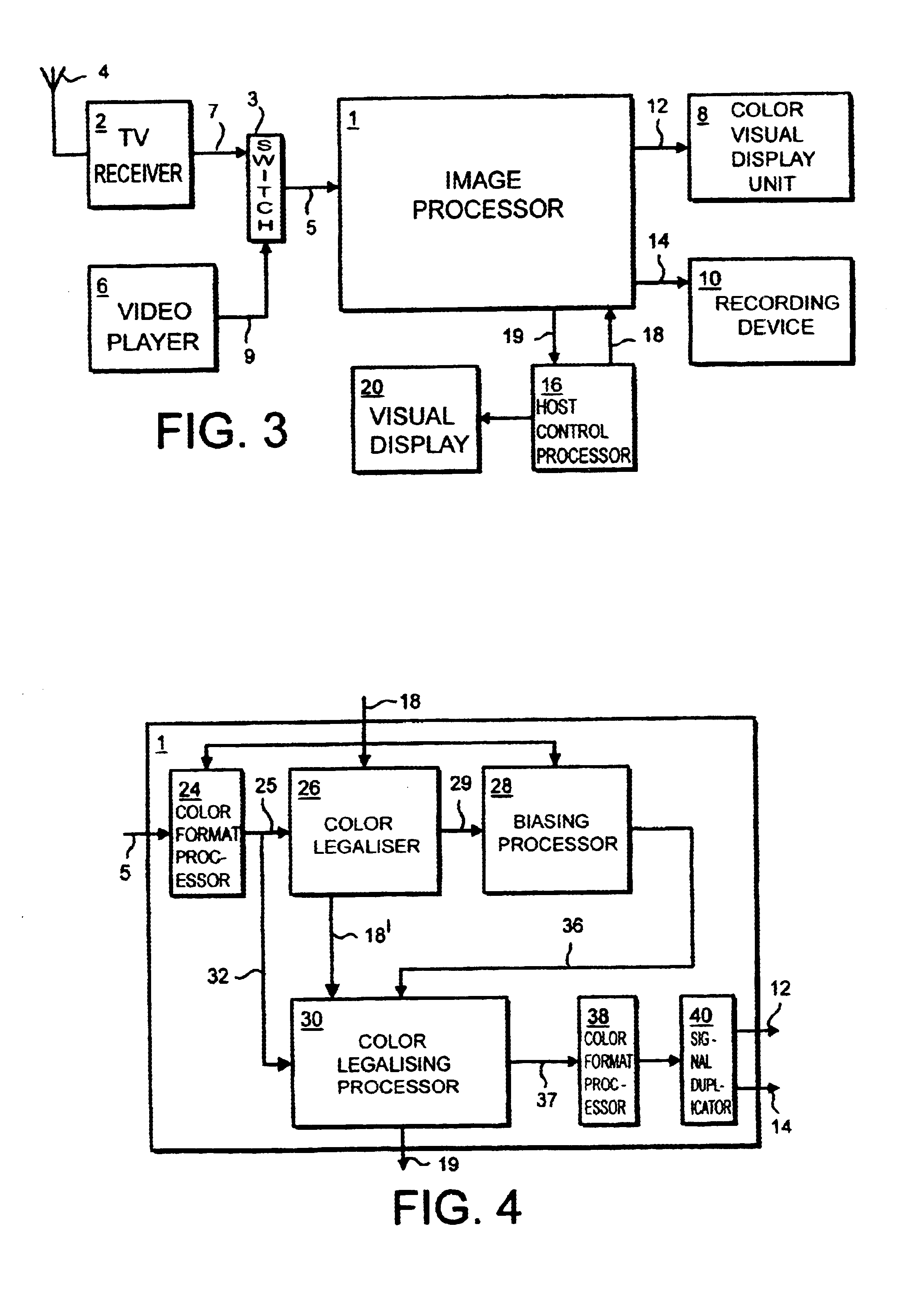
An image processing apparatus which provides a first example embodiment of the present invention is shown in FIG. 4. In FIG. 4, the input samples in YCrCb 4:2:2 format are received from the channel 5 by the image processing apparatus and fed to a colour format processor 24. The colour format processor operates to convert the input signal samples from YCrCb 4:2:2 format into 4:4:4 format, and to produce on an output 25 either RGB colour reference signal samples or YUV colour difference signal samples or both, in dependence upon control signals fed from the control channel 18, which indicate which of the legalising methods are to be used and therefore in which format the signal samples should be. The input signal samples in RGB form and YUV form are fed to an adjustment factor generator 26 via a connecting conductor 25. An output of the adjustment factor generator 26 is connected to a biasing processor 28, via a channel 29. An output of the biasing processor 28 is connected to a first...

second embodiment

A second embodiment of the present invention will now be described with reference to FIG. 11 where parts also appearing in FIG. 3 bear the same numerical designations. In FIG. 11, the image processing apparatus 1 is shown to receive the input signal samples via the channel 5 and as with the first embodiment, these signal samples are in the CCIR-601 YCrCb 4:2:2 format. The input signal samples are first fed to a colour conversion processor 110 which operates to scale the signal samples corresponding to the two CrCb chrominance signals so that they are converted to the of form of the two UV chrominance signal samples. Furthermore to allow for quantisation errors which may occur in the input signal samples the word length with which each of the input signal samples is represented increased from ten bits to fifteen bits. This provides an increased resolution from which quantisation errors and rounding effects can be detected and processed, so that these errors can be avoided. Coupled to...


PUM


Abstract

An image processing apparatus operates to process input signal samples representative of at least part of a color video image to produce legal color signal samples representative of a legal color version of the image. The apparatus comprises an adjustment factor generator, which operates to generate a plurality of adjustment factors which when combined with the input signal samples have an effect of converting illegal color pixels of the color image into legal color pixels, an adjustment factor biasing processor coupled to the adjustment factor generator, which operates to change the adjustment factors by combining each of the adjustment factors with a biasing constant, and a color legalizer coupled to the biasing processor, which operates to combine the biased adjustment factors with the input signal samples to produce the legalized color signal samples. This has an effect of increasing or decreasing the effect of the adjustment factors to increase or decrease a possibility of illegal pixels remaining in the legalized color image. The image processing apparatus may operate with input signal samples in the form having red, green or blue components, or in a form having luminance and chrominance components, or indeed in other forms.

Description

1. Field of the InventionThe present invention relates to methods of processing signal samples representative of a colour video image to produce a legalised colour version of the image. Furthermore, the present invention relates to apparatuses for processing signal samples representative of a colour video image to produce a legalised colour version of the image.2. Description of the Prior ArtIt is well known that the colours of the rainbow, which correspond to light with a range of wavelengths which is visible to the human eye, can be represented from combinations of the colours red, green and blue. For this reason colour television and video images are generated by separating the red, green and blue components of the images and sampling these components at spatially separated sampling points within the image. For example, colour television cameras are provided with a dichronic element which separates the colours of an image formed within a field of view of the camera into red, gree...

Claims


Application Information

Patent Timeline
Patent Type & Authority Patents(United States)
IPC IPC(8): H04N9/68H04N9/64G06T1/00H04N1/46H04N1/60H04N11/00H04N11/24
CPCH04N9/646H04N9/68
Inventor MCINTYRE, JAMES HENDRIE
Owner SONY UK LTD
Why Eureka
Try Eureka