

System for reducing adjacent-channel interference by pre-linearization and pre-distortion
a technology of adjacent channels and pre-linearization, which is applied in the direction of transmitter/receiver shaping networks, amplifiers, transmission, etc., can solve the problems of difficult to adapt the amplifier to a load, the bandpass filter connected to the output of the non-linear channel is subject to high demands, and the pre-distortion in the radio frequency range rarely provides an adequate compensation
- Summary
- Abstract
- Description
- Claims
- Application Information
AI Technical Summary
Benefits of technology
Problems solved by technology
Method used
Image

Examples
first embodiment
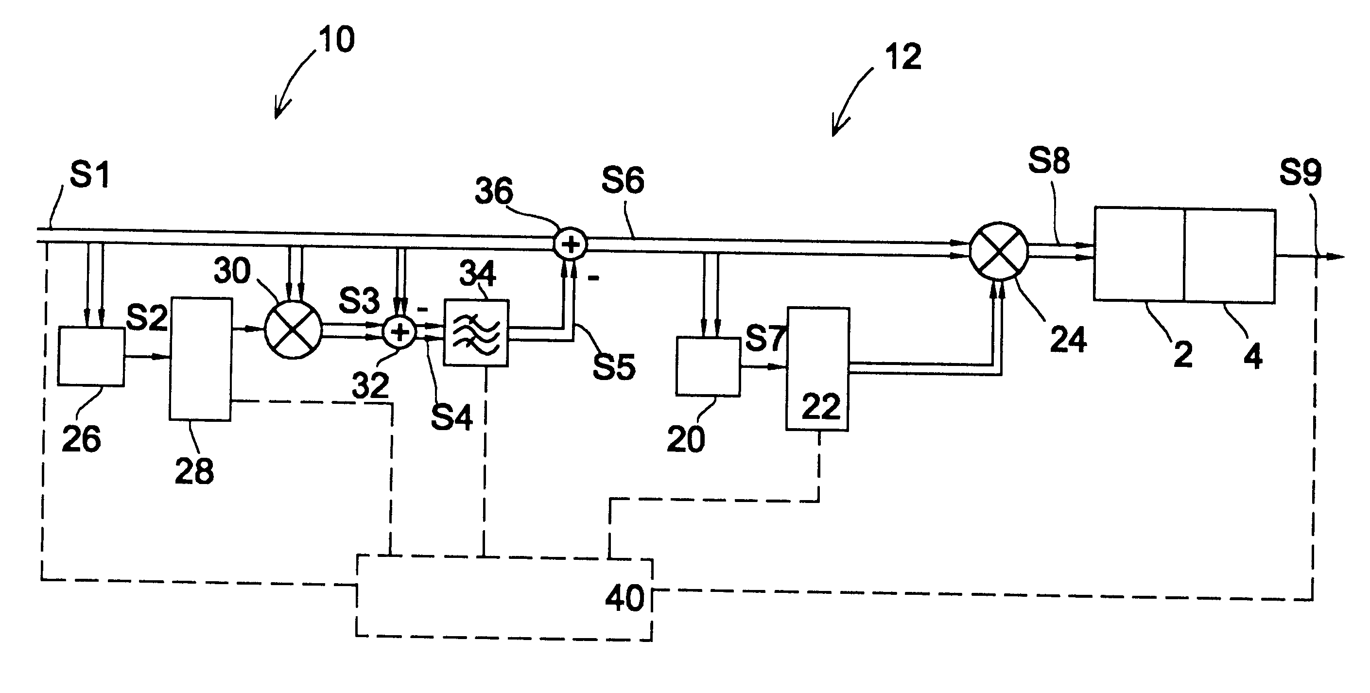
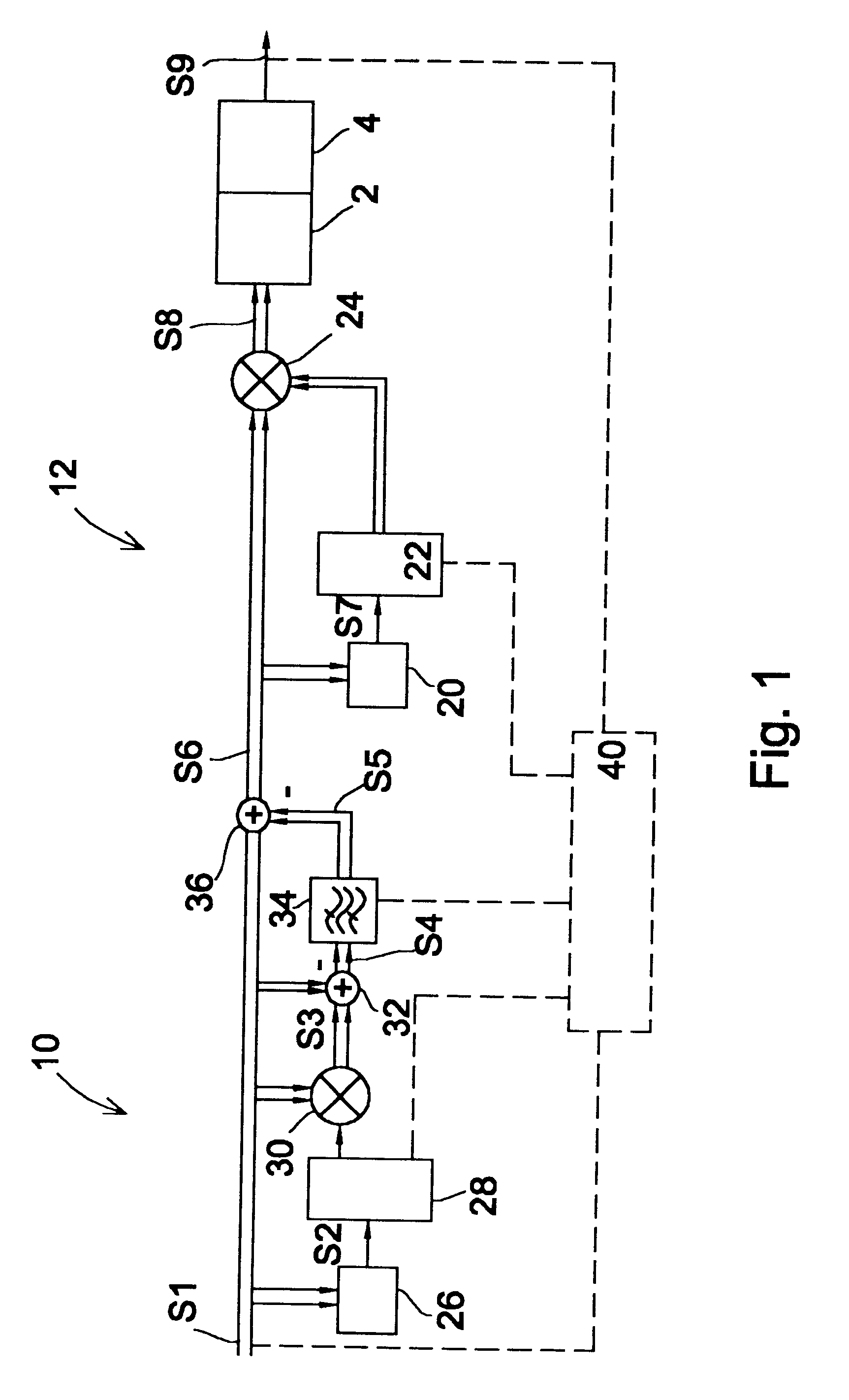
A circuit for reducing adjacent-channel interference by pre-linearizing and pre-distorting an input signal according to the present invention is shown in FIG. 1 along with an upconverter 2 and a power amplifier 4 of a RF output stage. It is to be noted that the upconverter 2 comprises a digital-to-analog converter in case a digital input signal is applied thereto.
As can be seen from FIG. 1, the inventive circuit for reducing adjacent-channel interference comprises a pre-linearizing unit 10 and a pre-distorting unit 12. The pre-linearizing unit 10 and the pre-distorting unit 12 are connected in series, wherein the input of the pre-distorting unit is connected to the output of the pre-linearizing unit.
Before the pre-linearizing unit 10 is described in detail, reference is made to the pre-distorting unit 12. In principle, the pre-distorting unit 12 works like a prior art pre-distorting unit, as described, for example, in U.S. Pat. No. 5,049,832. In the pre-distorting unit 12, a complex...
second embodiment
an inventive circuit for reducing adjacent-channel interference by pre-linearizing and pre-distorting an input signal to be transmitted via a power amplifier is shown in FIG. 4. Components that are identical in FIGS. 1 and 4 are designed by identical reference numerals. In connection with FIG. 4, only differences between the circuits shown in FIGS. 1 and 4 are described hereinafter.
As can be seen from FIG. 4, only one estimator 26 is used in order to produce an estimation signal based on the power of the input signal S1. The estimation signal is used to access both a real coefficient look-up table 28' and a complex coefficient table 22'. The real coefficient look-up table 28' is used in the pre-linearizing unit of FIG. 4, which is composed of the elements 26, 28', 30, 32, 34 and 36. The complex coefficient look-up table 22' is used in the pre-distorting unit shown in FIG. 4, which is composed of elements 26, 22' and 24. Thus, the embodiment shown in FIG. 4 represents a "interleaved"...
PUM
 Abstract
Description
Claims
Application Information