
Hydraulic weighing apparatus and method

a weighing apparatus and hydraulic technology, applied in the direction of weighing apparatus, weighing apparatus using fluid action balancing, instruments, etc., can solve the problems of increasing the time required to complete the waste collection service, inconvenient in terms of efficiency, and much too slow for static weighing in a waste collection environmen

Inactive Publication Date: 2003-09-30
TEK SOLUTIONS
View PDF7 Cites 15 Cited by
  • Summary
  • Abstract
  • Description
  • Claims
  • Application Information

AI Technical Summary

Benefits of technology

In one embodiment, a hydraulic pump which pumps fluid to the hydraulic actuator to move the lifting arm operates at a constant volume flow rate during most of the movement of the arm, except for the periods when the arm stops and starts moving. The pressure measurements made by the first and second pressure sensing means are taken between two set points in most cases, while volume flow rate is theoretically constant and the arm is ideally travelling at a constant velocity, thus obviating the requirement for any accelerometer or other means for measuring the acceleration of the arm.
The system simply uses the existing hydraulics of the vehicle and it is not necessary to fit load cells or other weight sensing devices to the lifting mechanism to make weight measurements. Thus, the system of the present invention can be implemented relatively simply and without major mechanical modifications.

Problems solved by technology

This can only be achieved by separating recyclable material and biodegradable materials that previously went to landfill, from waste.
However, static weighing is much too slow for use in a waste collection environment, since such technology, and other weighing technology requires a set period of time to perform the weighing function.
This would increase the time required to complete the waste collection service and would be unacceptable in terms of efficiency.
Although dynamic weighing systems have been proposed, most of these systems are unreliable and inaccurate often because they fail to compensate for variables in the weighing process.

Method used


Image

  • Hydraulic weighing apparatus and method
  • Hydraulic weighing apparatus and method
  • Hydraulic weighing apparatus and method

Examples


Embodiment Construction

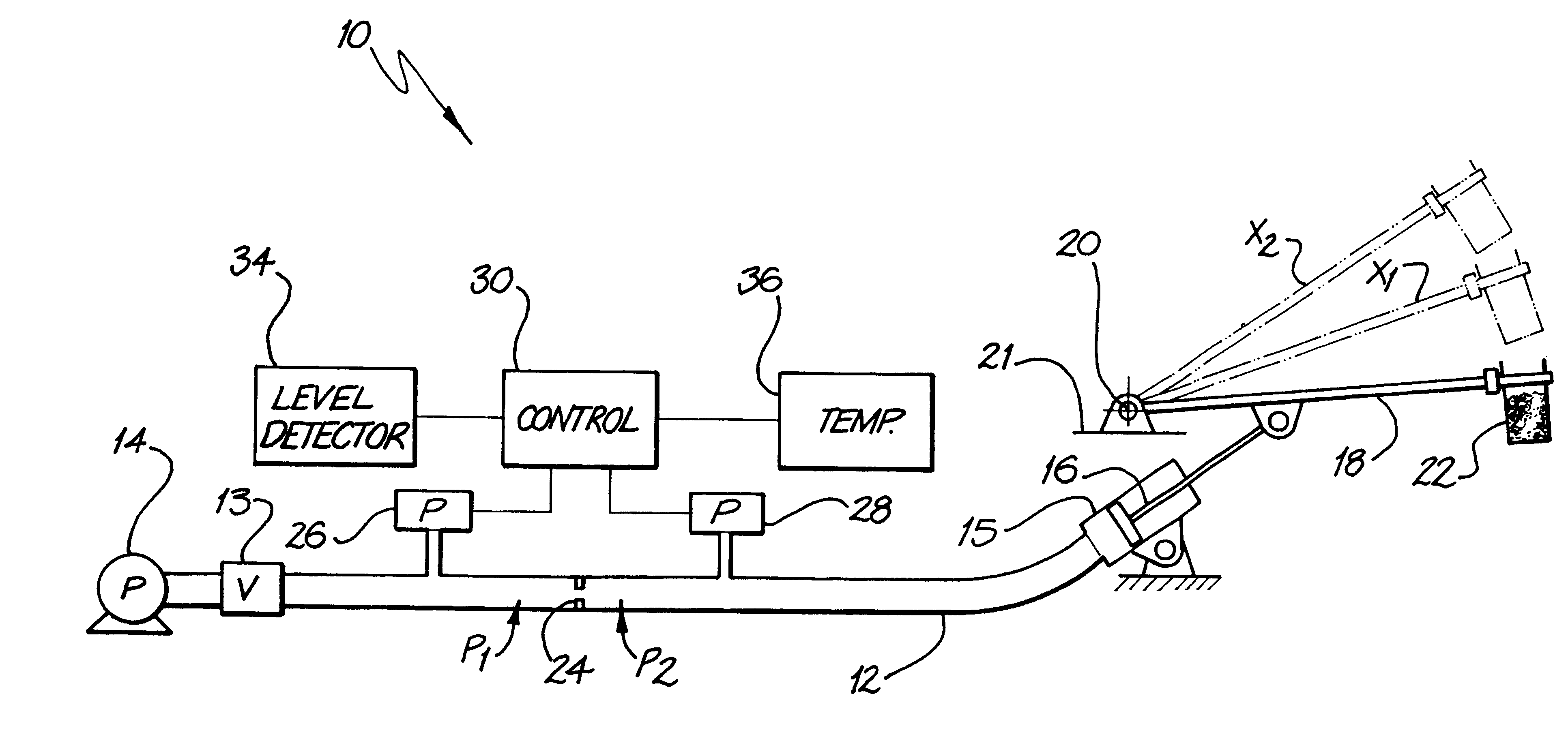
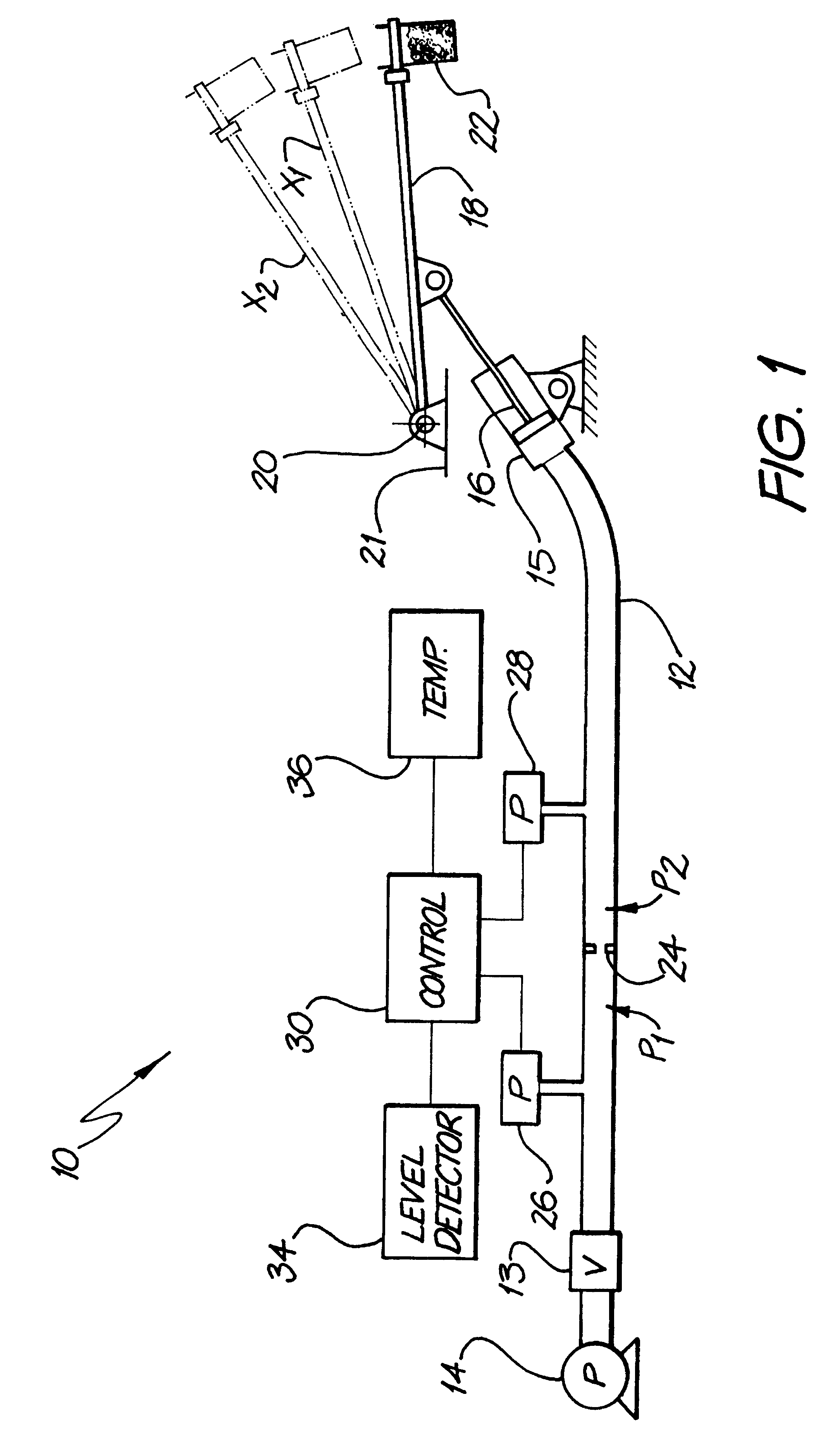
Referring to the drawing, FIG. 1 shows a schematic diagram of a dynamic weight measuring apparatus embodying the present invention 10. The Figure is not to scale.

The apparatus includes a pump 14, which supplies hydraulic fluid, typically an oil, via a control valve 13 and the flow line 12 to a hydraulic cylinder 15 and piston 16 arrangement which is operatively connected to a lifting arm 18. The pump may be, but is not necessarily, a constant volume flow rate pump. One end of the arm is mounted on a pivot 20 and the other end carries a garbage bin or the like 22. Clearly movement of the piston 16 in cylinder 15 causes the arm 18 to rotate about the pivot 20 lifting or lowering the bin 22. The cylinder and piston could be replaced by a rotary actuator in an alternative embodiment. The arm is carried on a base frame schematically represented by the line 21 which should ordinarily be horizontally oriented.

There is an orifice 24 disposed in the hydraulic line 12 between the cylinder 15 ...


PUM


Abstract

A hydraulic lifting and weighing system particularly for refuse collection vehicles and the like and includes means for dynamically weighing garbage. The system includes a hydraulic actuator operable to move a lifting arm and takes two measurements of the pressure of the hydraulic fluid in the system as the arm raises a waste bin whose weight is to be measured. The weight of the bin is calculated by multiplying the pressure by a factor determined by calibration with known weights. Weights are calculated based on the measurements of pressure and the result averaged. The system compensates for variations in hydraulic flow characteristics. The system includes means for compensating for variations in the inclination of the vehicle.

Description

This invention relates to a hydraulic weighing apparatus and method. In particular, the invention relates to an apparatus and method for dynamic weighing, in which the weight to be measured is moved by a hydraulic cylinder, a rotary actuator, or the like, and in particular, to such a method and apparatus for use in weighing commercial and / or domestic waste1. Background of the InventionWaste or refuse is produced by both domestic households and commercial organisations. The service of waste removal is commonly carried out by municipal councils, particularly in the case of domestic households. In some arenas, waste is also collected by commercial organisations often acting on behalf of municipal councils. Most domestic households, pay a fixed rate for disposal of refuse which is independent of the amount of refuse the household produces. However, as councils become increasingly concerned about the environment, the cost of landfill, and the need to encourage people to recycle more hous...

Claims


Application Information

Patent Timeline
Patent Type & Authority Patents(United States)
IPC IPC(8): G01G19/10G01G19/08G01G5/00G01G5/04
CPCG01G5/04G01G19/10G01G23/01G01G23/48
Inventor CRESWICK, RICHARD
Owner TEK SOLUTIONS
Learn More