
Structure for stator of reciprocating motor
a technology of stator and reciprocating motor, which is applied in the direction of dynamo-electric components, dynamo-electric machines, magnetic circuit shapes/forms/construction, etc., can solve the problems of increasing the amount of permanent magnets and increasing production costs
- Summary
- Abstract
- Description
- Claims
- Application Information
AI Technical Summary
Benefits of technology
Problems solved by technology
Method used
Image

Examples
first embodiment
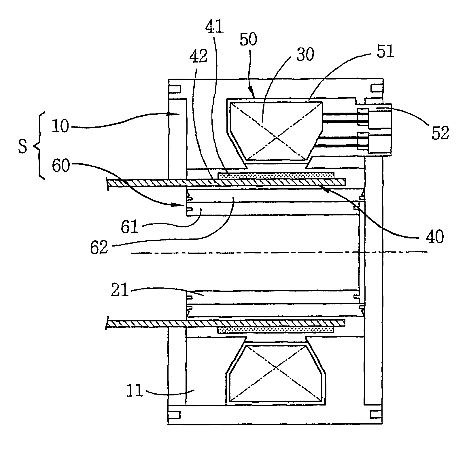
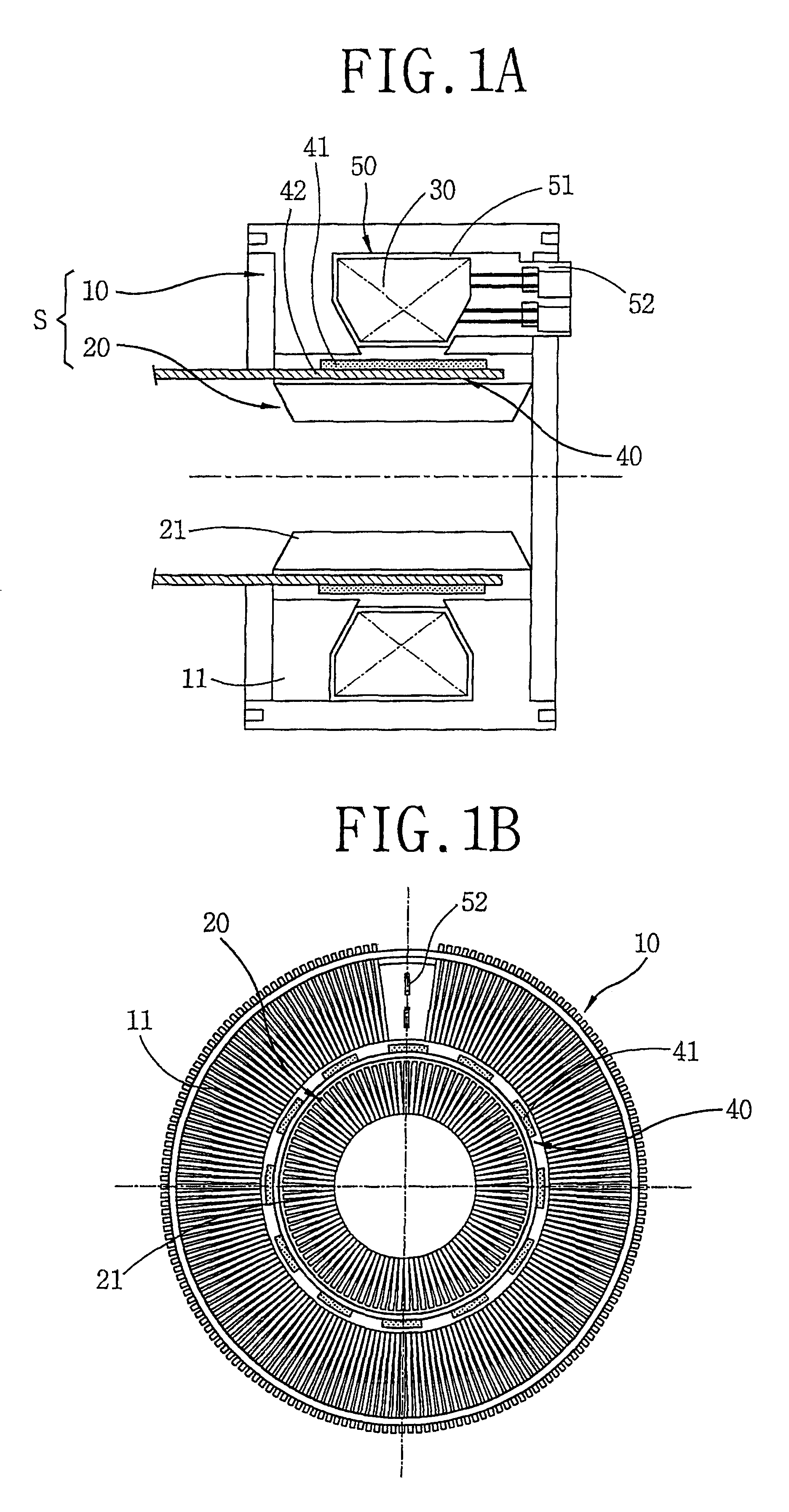
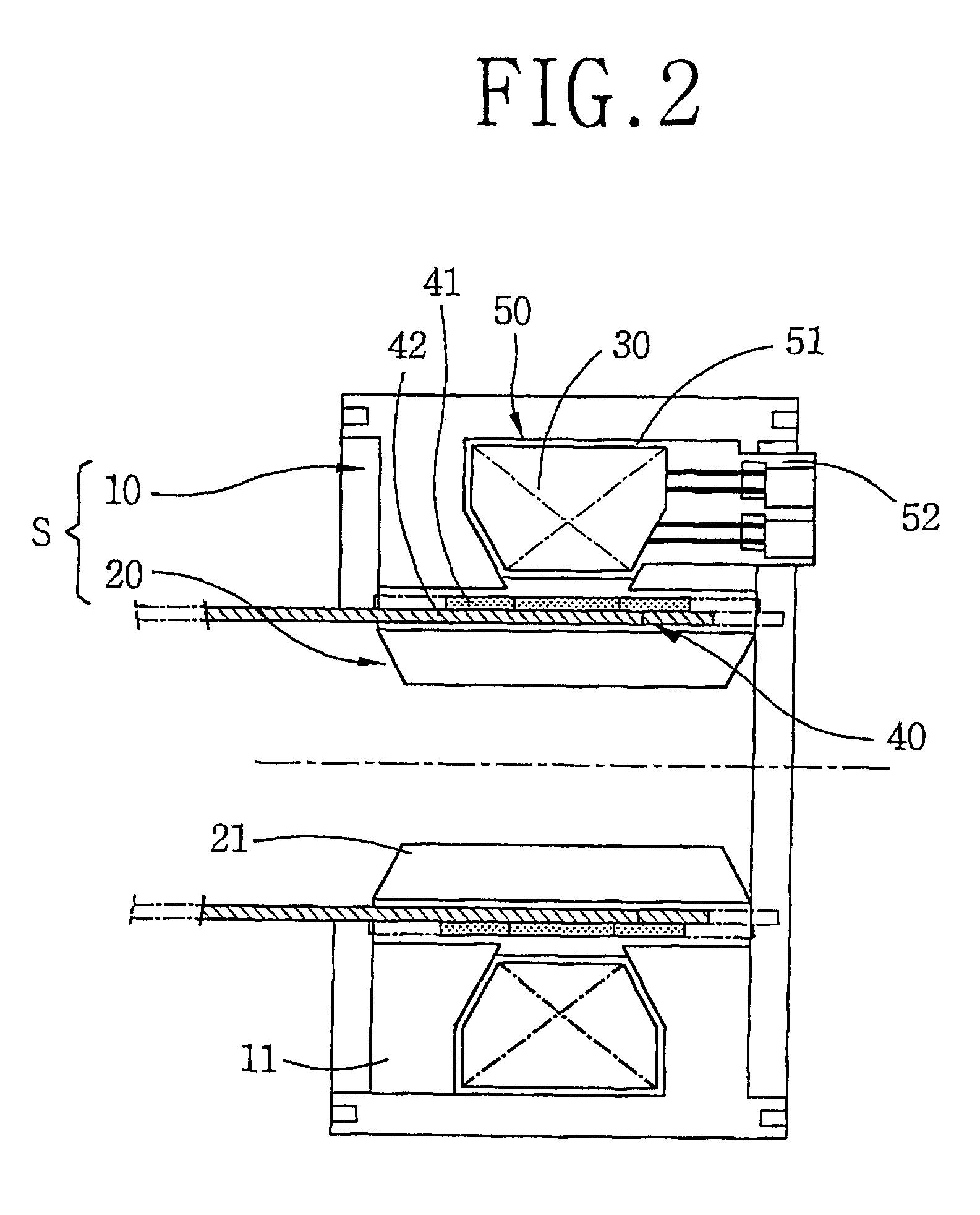
A stator structure of a reciprocating motor in accordance with the present invention includes a stator (S) having a hollow cylindrical outer core 10 and a hollow cylindrical inner core 60 inserted inside the outer core 10; a winding coil 30 coupled inside the outer core 10; and an armature 40 movably inserted between the outer core 10 and the inner core 60.
The outer core 10 is formed as a stacked body that a plurality of thin lamination sheets 11 in a predetermined shape are radially stacked to make a hollow cylindrical form.
The outer core 10 is formed at the outer circumferential face of the bobbin.
The bobbin 50 includes a coil winding part 51 formed in an annular shape and a terminal part 52 formed at a side of the coil winding part 51.
The winding coil is constructed that a coil is wound at the coil winding part 51 of the bobbin 50 in a multi-layer, and the wound coil is connected to the terminal part 52.
The plurality of lamination sheets 11 of the outer core 10 are radially stack...
second embodiment
The stator structure of the reciprocating motor in accordance with the present invention will now be described.
FIG. 10 is a front-sectional view of a stator structure of a reciprocating motor in accordance with a second embodiment of the present invention, and FIG. 11 is a side view showing a reciprocating motor core stacking structure of the stator structure of a reciprocating motor in accordance with the second embodiment of the present invention.
As shown in FIGS. 10 and 11, a reciprocating motor adopting a core stacking structure in accordance with the second embodiment of the present invention includes a stator (S) having a hollow cylindrical outer core 110 and a high density stack-type inner core 160 with a hollow cylindrical form inserted into the outer core 110, a winding coil 30 coupled inside the outer core 110, and an armature 140 having a permanent magnet 141, movably inserted between the outer core 10 and the high density stack-type inner core 160. The outer core 10 is f...
third embodiment
The stator structure of the reciprocating motor in accordance with the present invention will now be described with reference to FIGS. 16 and 17.
FIG. 16 is a front-sectional view of a stator structure of a reciprocating motor in accordance with a third embodiment of the present invention, and FIG. 17 is a side-sectional view of a stator structure of a reciprocating motor in accordance with the third embodiment of the present invention.
As shown in FIGS. 16 and 17, a reciprocating motor includes a stator (S) having a hollow cylindrical outer core 210 and a composite inner core 260 inserted into the outer core 210 with a predetermined space therebetween; a winding coil coupled inside the outer core 210, and an armature 240 having a permanent magnet 241 and movably inserted between the outer core 210 and the composite inner core 260.
The outer core 210 is formed such that a plurality of thin lamination sheets 211 in a predetermined form are radially stacked to make a hollow cylindrical f...
PUM
 Abstract
Description
Claims
Application Information