Anti-reflection member and cathode ray tube

a technology of anti-reflection and cathode ray tube, which is applied in the direction of optical elements, identification means, instruments, etc., can solve the problems of large difference in intensity between the center portion and the corner portion of the screen, increase the thickness of the corner and increase the thickness of the corner portion and the center portion of the panel glass portion. , to achieve the effect of reducing the reflectance and reducing the reflectan

Inactive Publication Date: 2003-09-30
SONY CORP
View PDF1 Cites 35 Cited by
  • Summary
  • Abstract
  • Description
  • Claims
  • Application Information

AI Technical Summary

Benefits of technology

An object of the present invention is to provide an anti-reflection member which has an electrical conductivity and a light absorptivity, and which is capable of not only reducing a reflectance against light incident from a front surface side of an anti-reflection film but also sufficiently reducing a reflectance against light incident from a back surface side of the antireflection film.
Not only reflection of light incident from a front surface side of the anti-reflection film side, that is, the sixth film side, but also reflection of light incident from a back surface side of the anti-reflection film, that is, the light transmittable substrate, side can be sufficiently prevented.

Problems solved by technology

On the other hand, along with the recent tendency to flatten panel glass portions of cathode ray tubes, a thickness of each corner portion of the panel glass portion has come to be increased, with a result that the difference in thickness between the corner portion and a center portion of the panel glass portion has become large.
Accordingly, a display apparatus using such a cathode ray tube has an inconvenience that the difference in intensity between the center portion and the corner portion of a screen becomes large.
As a result, the contrast performance of a display image or the like is significantly degraded, thereby causing the problem that an image is doubly displayed.
For such an optical filter, however, the reflectance against light emitted from the front surface side of the multi-layer film is only about 10% in a visible light region, and, therefore, it fails to obtain a practical anti-reflection characteristic.

Method used


Image

  • Anti-reflection member and cathode ray tube
  • Anti-reflection member and cathode ray tube
  • Anti-reflection member and cathode ray tube

Examples


Embodiment Construction

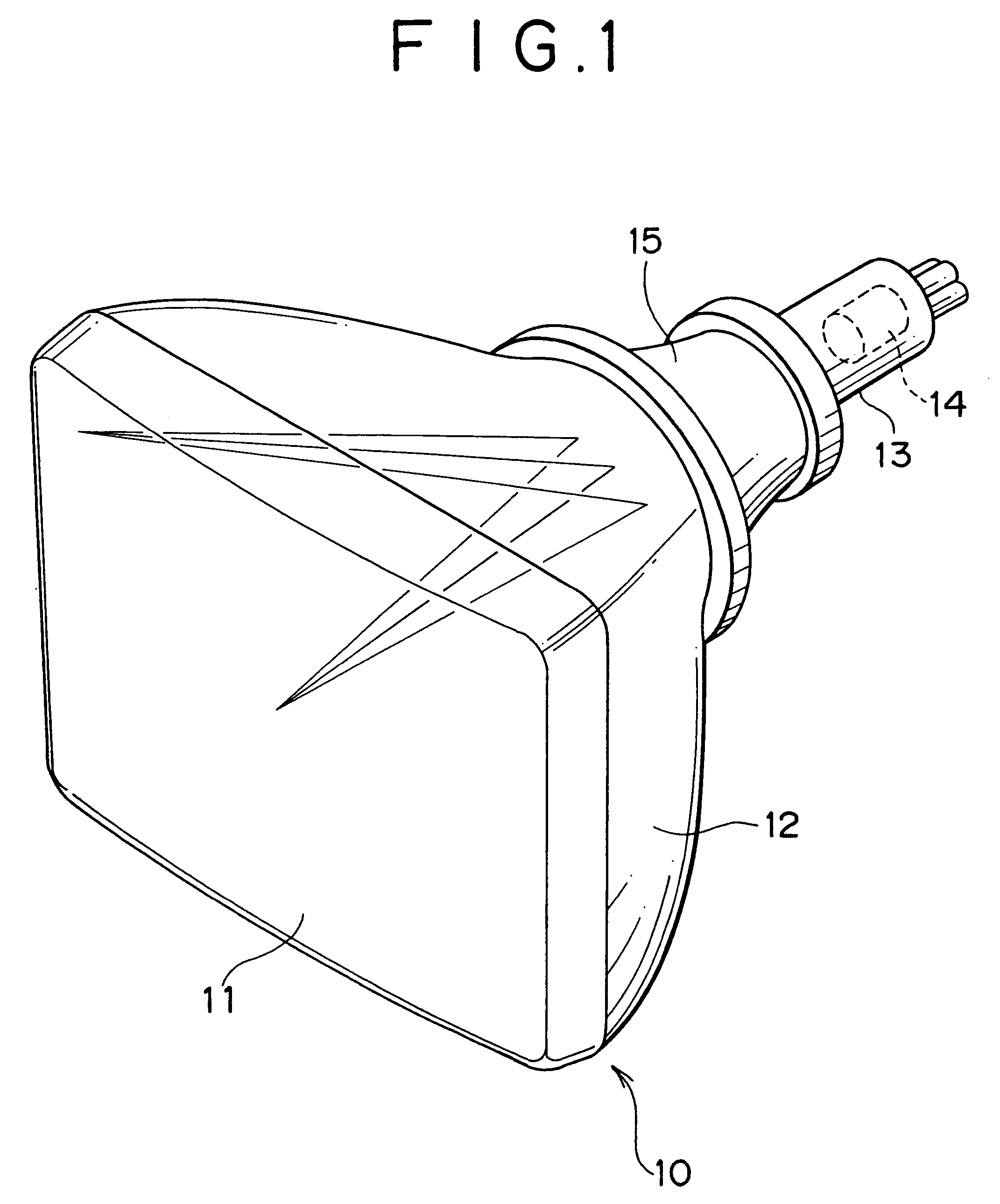
Hereinafter, a preferred embodiment in which the present invention is applied to a cathode ray tube will be described in detail with reference to the accompanying drawings.

FIG. 1 is a schematic perspective view showing an entire configuration of a cathode ray tube to which the present invention is applied.

Referring to FIG. 1, a main body of a cathode ray tube 10 includes a panel portion 11, a funnel portion 12, and a neck portion 13.

A phosphor screen composed of red, green and blue phosphors arrayed in a specific pattern is provided on an inner surface of the panel portion 11. An electron gun 14 as an emission source of electron beams is provided in the neck portion 13. A deflection yoke 15 is mounted to a cone portion extending from the funnel portion 12 to the neck portion 13. An electron beam is scanned in the vertical and horizontal directions by the deflection yoke 15.

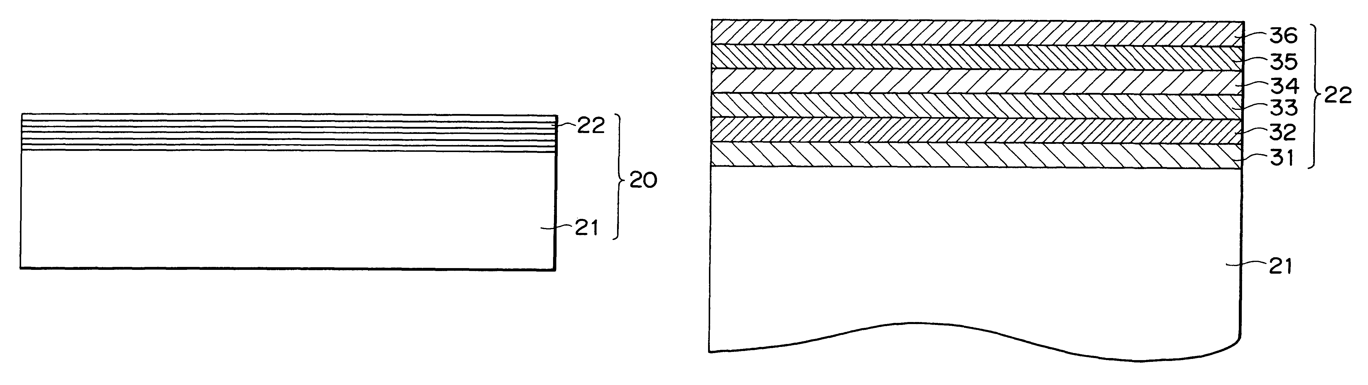
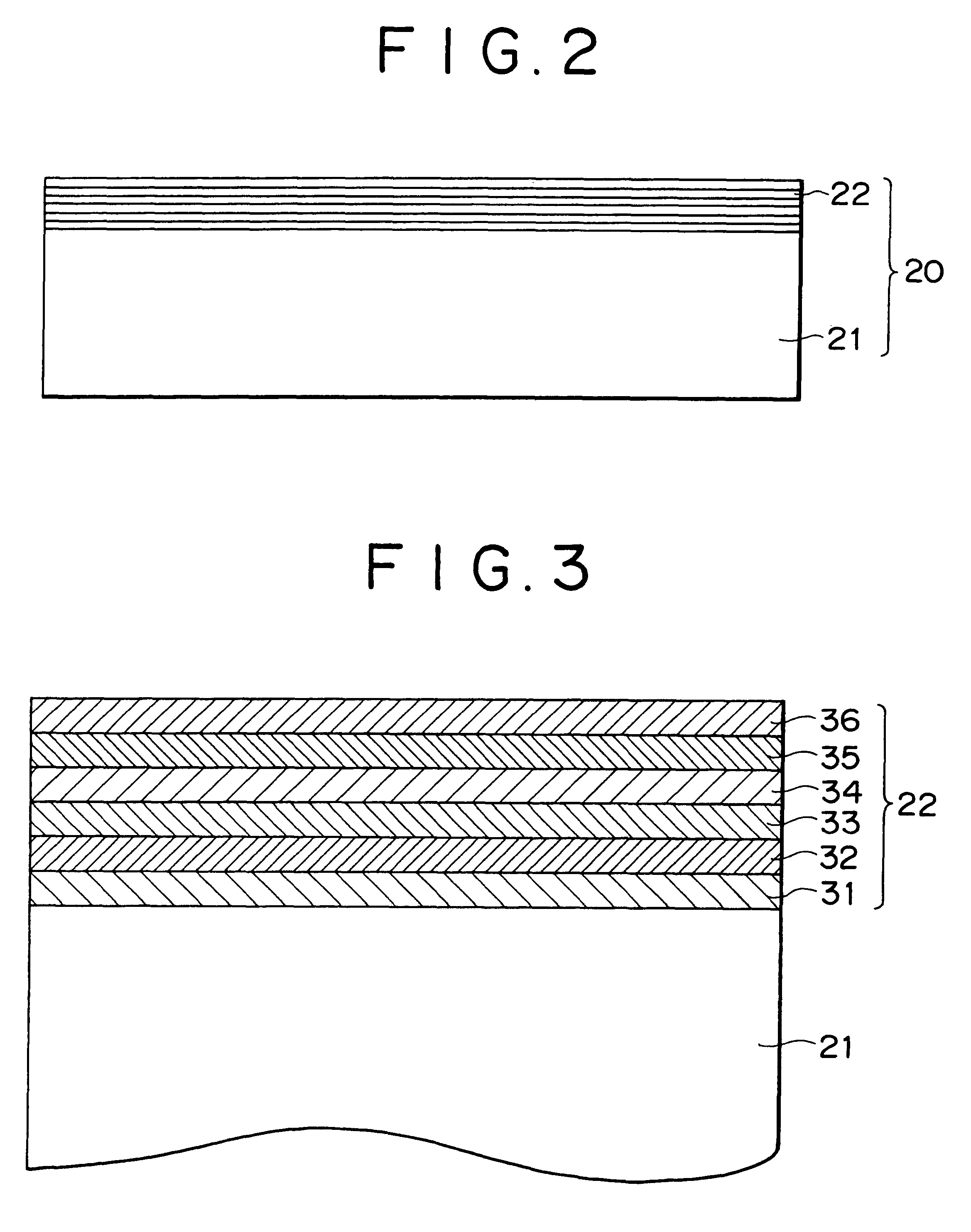
FIG. 2 is a sectional view of an anti-reflection member constituting a panel front surface portion of the panel...


PUM

PropertyMeasurementUnit
thicknessaaaaaaaaaa
thicknessaaaaaaaaaa
optical thicknessaaaaaaaaaa

Abstract

The present invention relates to an anti-reflection member and a display. The anti-reflection member includes a light transmittable substrate and an anti-reflection film. The anti-reflection film includes a first film formed from a light transmittable material, a second film formed from a light absorptive material having an electrical conductivity, a third film formed from a light transmittable material, a fourth film formed from a light transmittable material having an electrical conductivity, a fifth film formed from a light transmittable material having a high refractive index, and a sixth film formed from a light transmittable material. The anti-reflection member can prevent reflection of not only light coming from the first film side but also light coming from the sixth film side, thereby preventing an image from being doubly displayed on a screen.

Description

The present invention relates to an anti-reflection member including a light transmittable substrate and an anti-reflection film, and, particularly, to an antireflection member suitable for a cathode ray tube.Anti-reflection members applied to front panels of display apparatuses or the like have been required to have electrically conductive and light absorptive characteristics for improving the contrasts of display images and the ergonomics of users.On the other hand, along with the recent tendency to flatten panel glass portions of cathode ray tubes, a thickness of each corner portion of the panel glass portion has come to be increased, with a result that the difference in thickness between the corner portion and a center portion of the panel glass portion has become large. Accordingly, a display apparatus using such a cathode ray tube has an inconvenience that the difference in intensity between the center portion and the corner portion of a screen becomes large.As electrically co...

Claims


Application Information

Patent Timeline
Patent Type & Authority Patents(United States)
IPC IPC(8): G02B1/11G02B1/10H01J29/89C03C17/34G02B1/115G02B1/16G09F9/00H01J29/88
CPCG02B1/116H01J29/896H01J2229/8918
Inventor ARAKI, SOYASUMIDA, TAKAO
Owner SONY CORP
Why Eureka
Try Eureka