Optical bus system and method

a technology of optical bus and optical transmission, applied in the direction of electromagnetic transmission, electrical equipment, transmission, etc., can solve the problems of increasing the cost of connectors for transmitting signals from one unit to another, increasing the space requirement, and increasing the cost of hard-wired bus systems

Inactive Publication Date: 2003-09-30
IBM CORP
View PDF11 Cites 43 Cited by
  • Summary
  • Abstract
  • Description
  • Claims
  • Application Information

AI Technical Summary

Problems solved by technology

Conventional hard-wired bus systems are relatively expensive and have disadvantages.
In so far as electronics technology is experiencing increasing integration, connectors for transmitting signals from one unit to another are becoming ever more expensive or reliability can only be achieved at a very high cost.
Added to this is an ever greater space requirement
However, in this process optical signals are still only transmitted from one special point to another special point inside optical fibres.
The biggest problem appears to lie in the fact that proposed optical bus systems, which could perhaps be used to connect a large number of electronic components, are very much more expensive and are only to be made as reliable as the hard-wired bus systems they are intended to replace at considerable expense.
Exotic optical components, precise alignment within the components and the size of the optical units have caused the application of optical technologies to fail in electronic systems in which a large number of components have to communicate with one another via a common bus system.
However, these systems have the disadvantage that either mutual interference restricts the applic...

Method used


Image

  • Optical bus system and method
  • Optical bus system and method
  • Optical bus system and method

Examples


Embodiment Construction

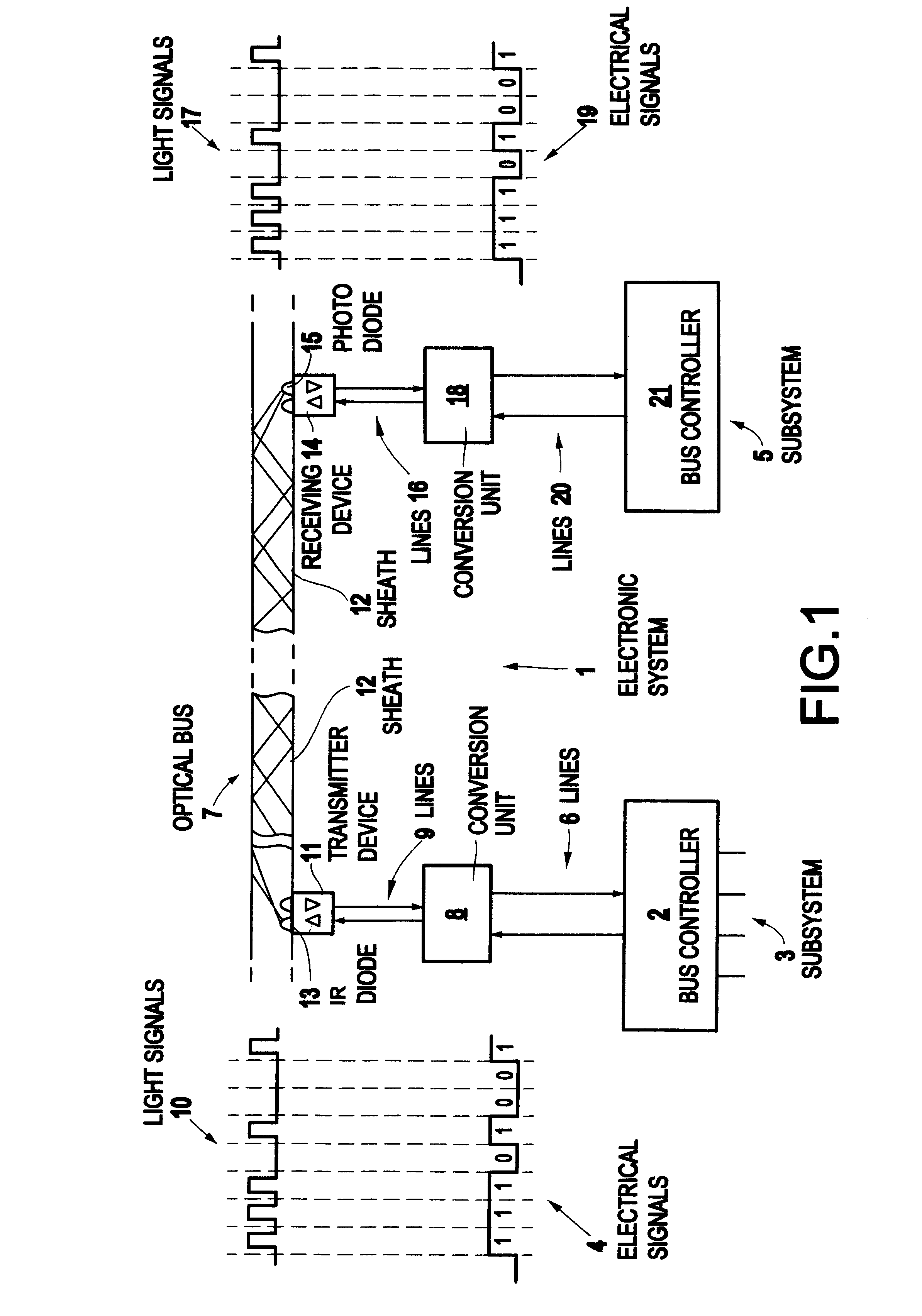
In the present example, the diffuse light used for optical transmission of the information consists of IR light. However, any other diffuse light can be used, e.g. diffuse laser light, electroluminescence etc. The use of light in the infrared wavelength range (for example 870 nm) as the transmission medium has the advantage that relatively cheap standard components, which are common in the consumer goods industry, such as IR diodes and possibly even photoresistors, can be used as transmitting or receiving devices. A simple transmission protocol is also available in the IrDA physical layer protocol. When using other transmitting and receiving devices, any other transmission protocol can naturally be used. A further advantage of the use of IR light consists in the fact that the system offers the best conditions for the creation of a "real-time system" due to the light transmission links separated from one another. This includes inter alia the fact that information which has a high pri...


PUM


Abstract

The invention relates to a bi-directional optical data transfer system. The data is transferred by a diffuse light between several electronic components with several transmission links, wherein each transmission link is provided with a covering to prevent the transmission links from interfering with each other.

Description

1. Field of the InventionThe present invention relates to a system for the bidirectional optical transmission of information. In particular, it relates to the connection of electronic components via a bidirectional optical bus system.2. Description of the Related ArtElectronic systems are normally composed of a series of fixed and / or variable electronic components (subsystems), which are connected to one another by a bus, which transports signals from one component to another.Thus digital computer systems for example are designed in this way. A number of individual cards or electronic components form subsystems, which are integrated into a bus system, which transports signals for data, storage addresses, interrupts and the like. One of these cards may carry a processor for the execution of application programs, while others in turn may contain controllers for workstations or displays, adapters for mass storage units or interfaces for LANs (Local Area Networks) etc. However, the subs...

Claims


Application Information

Patent Timeline
IPC IPC(8): G02B6/43H04B10/00H04B10/80
CPCG02B6/43H04B10/803
Inventor STAIGER, DIETER E.
Owner IBM CORP
Why Eureka
Try Eureka