Eureka AIR delivers breakthrough ideas for toughest innovation challenges, trusted by R&D personnel around the world.

Tissue cooling rod for laser surgery

a cooling rod and laser surgery technology, applied in the field of skin cooling, can solve the problems of significant damage, skin freezing, and insufficient heat removal of water cooled cold contact window devices, and achieve the effect of preventing unwanted surface tissue damage, preventing significant damage, and preventing skin freezing

Inactive Publication Date: 2003-10-14
RELIANT TECH INC
View PDF7 Cites 183 Cited by
  • Summary
  • Abstract
  • Description
  • Claims
  • Application Information

AI Technical Summary

Problems solved by technology

Cryogenic spray directly to the skin may reduce a skin temperature below 0 C but can freeze the skin and cause significant damage to it.
Typical cold contacting windows of the prior art utilize ice water at 0 C can cool the surface of the skin to as low as about 4 C. But prior art ice water cooled cold contact window devices are inadequate to remove enough heat to prevent unwanted surface tissue damage in many applications.
This method is normally not satisfactory.
The surface gets too cold and the subsurface layers are not sufficiently cooled so that unwanted damage occurs at the surface because the tissue gets too cold from the cryogen and / or unwanted damage occurs in the immediate subsurface layers because the tissue gets too hot from the laser beam.
The techniques do not work well for deeper, larger blood vessels.
The problem is how do you destroy the tissue below the epidermis without also destroying the epidermis and thus replacing an ugly wrinkle with an ugly scar.
But under skin damage is not uniform having irradiated and not irradiated healthy spots.
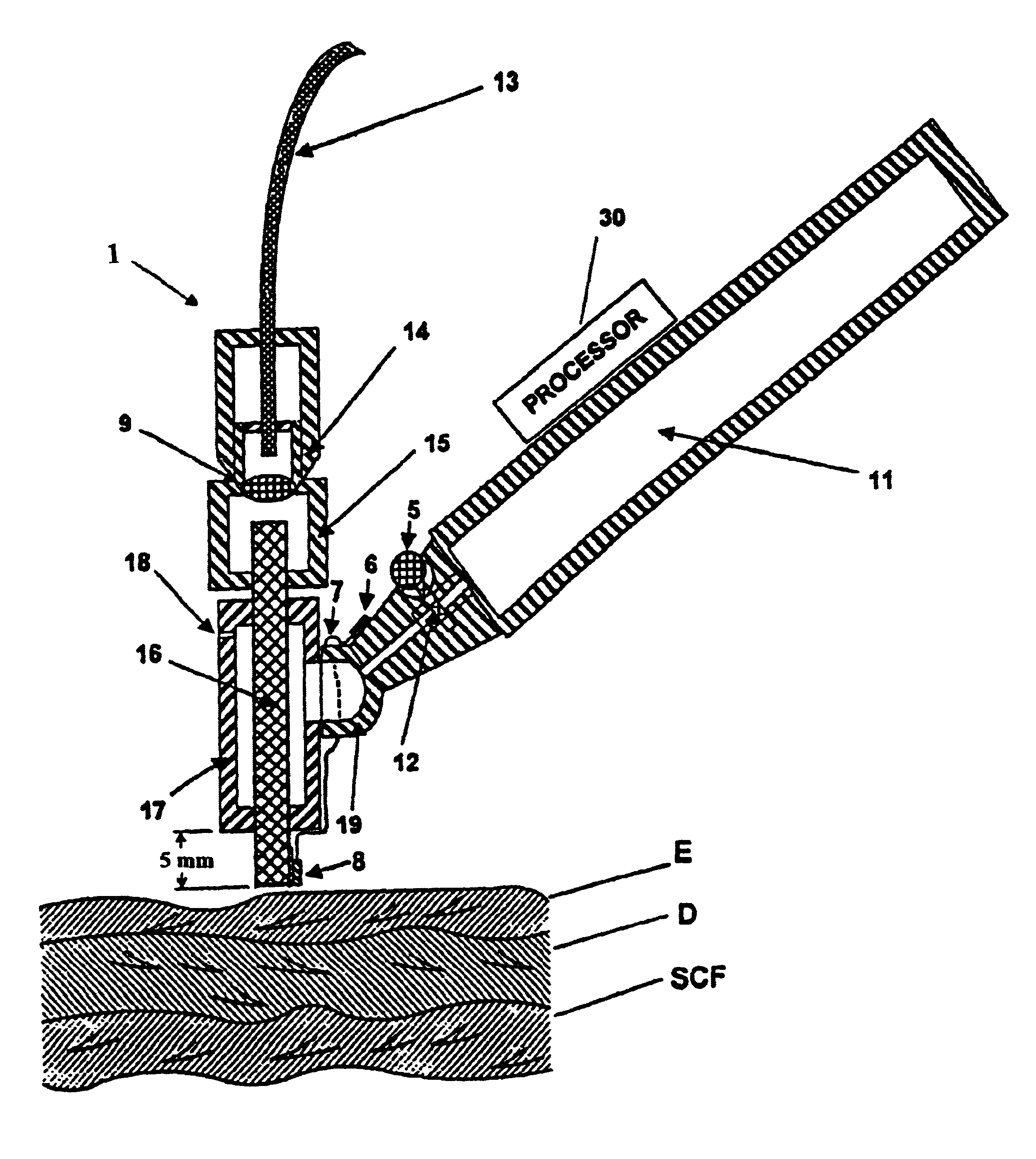
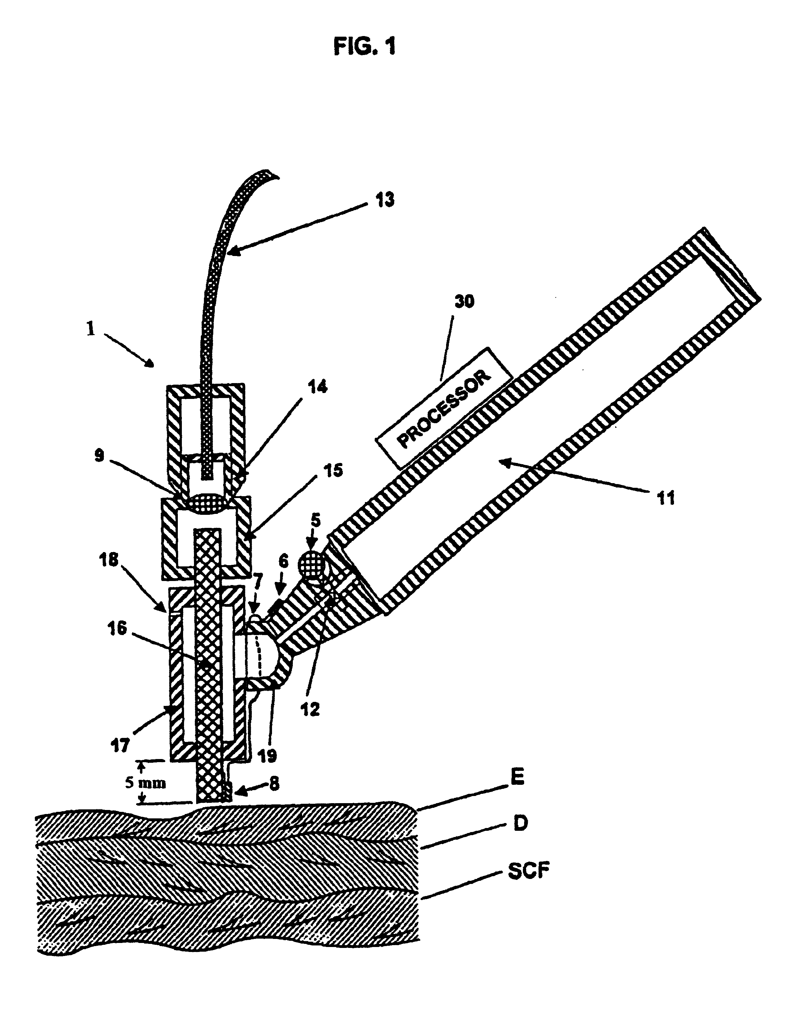
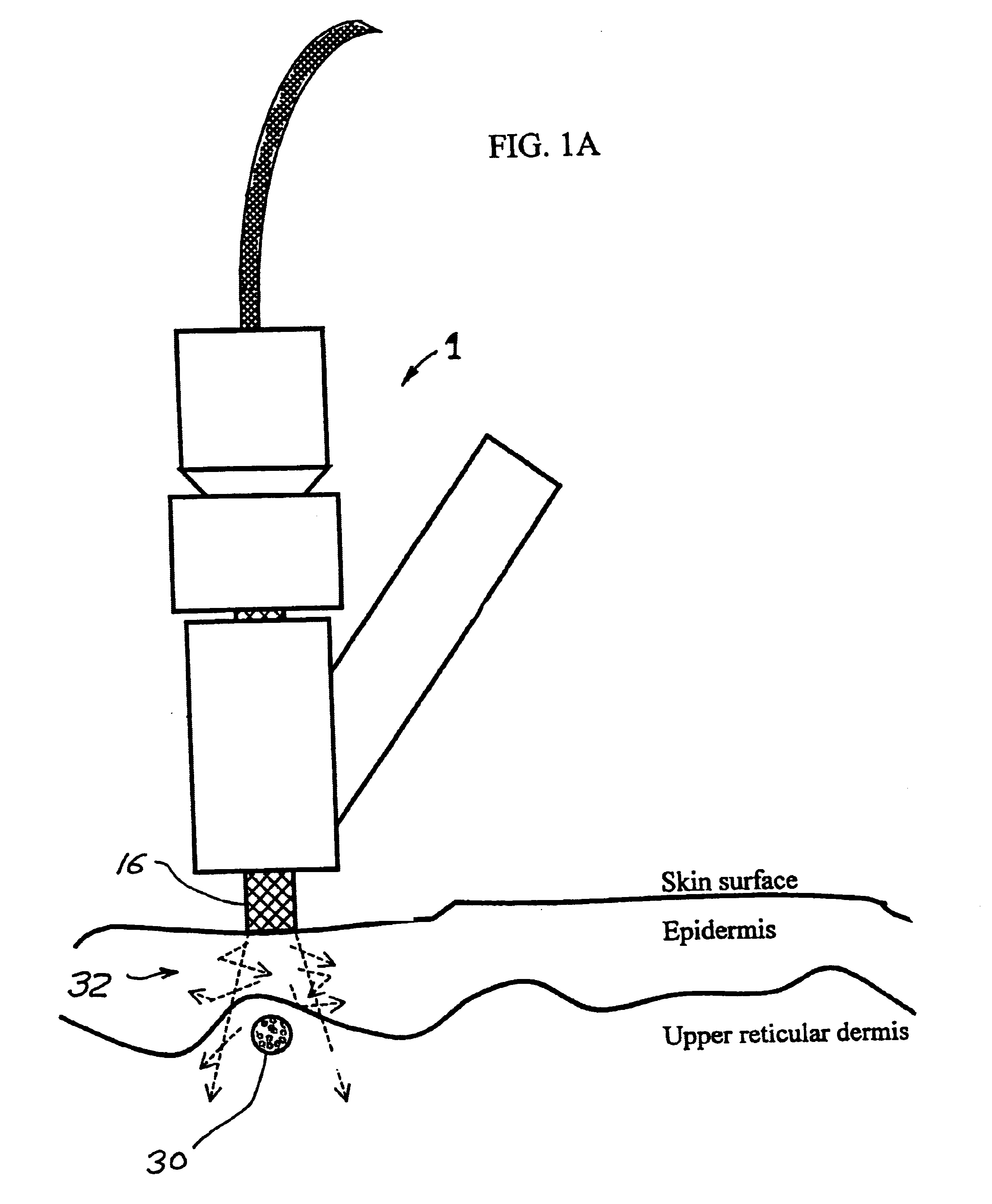
That is, surface tissue destruction can be provided by the very cold surface of the tip of the sapphire rod.

Method used


Image

  • Tissue cooling rod for laser surgery
  • Tissue cooling rod for laser surgery
  • Tissue cooling rod for laser surgery

Examples


Embodiment Construction

It is very important for all of these embodiments and in other embodiments that will be apparent to persons skilled in the art that the cooling rod has a very high thermoconductivity coefficient and low absorption of the irradiating light. The substance used for the cryogenic cooling can be chosen based on the particular application. The important thing is to use a proper time of cooling in order to reach a required low temperature of the tissue at the required depth. Persons skilled in the art will recognize that certain material and configuration of the rod, container, coolant and connector will be preferred for different skin type, different lesions and different applications. The reader should note that the preferred embodiment of this invention can be used without this laser to provide cryogenic treatment to surface skin lesions. The same skin cooling can be provided with about 1 / 10 the cryogen as direct open spray. An important application of the device for cryogenic treatment...


PUM


Abstract

A laser treatment device and process with controlled cooling. The device contains a cooling element with high heat conduction properties, which is transparent to the laser beam. A surface of the cooling element is held in contact with the tissue being treated while at least one other surface of the cooling element is cooled by the evaporation of a cryogenic fluid. The cooling is coordinated with the application of the laser beam so as to control the temperatures of all affected layers of tissues. In a preferred embodiment useful for removal of wrinkles and spider veins, the cooling element is a sapphire plate. A cryogenic spray cools the top surface of the plate and the bottom surface of the plate is in contact with the skin. In preferred embodiments the wavelength of the laser beam is chosen so that absorption in targeted tissue is low enough so that substantial absorption occurs throughout the targeted tissue. In a preferred embodiment for treating large spider veins with diameters in the range of 1.5 mm, Applicants use an Er:Glass laser with a wavelength of 1.54 microns.< / PTEXT>

Description

1. Prior Art Skin CoolingThe principal methods presently used for skin cooling before or during the laser treatment involve the use of a cold contacting window or cryogenic spray device. Cryogenic spray directly to the skin may reduce a skin temperature below 0 C but can freeze the skin and cause significant damage to it. Typical cold contacting windows of the prior art utilize ice water at 0 C can cool the surface of the skin to as low as about 4 C. But prior art ice water cooled cold contact window devices are inadequate to remove enough heat to prevent unwanted surface tissue damage in many applications.Three prior art techniques are described in the following United States patents: C. Chess, Apparatus for treating cutaneous vascular lesions, U.S. Pat. No. 5,486,172; Anderson et al., U.S. Pat. No. 5,595,568; and C. Chess, Method for treating cutaneous vascular lesions, U.S. Pat. No. 5,282,797. All of these devices and methods provide for the cooling of the skin down to temperatur...

Claims


Application Information

Patent Timeline
Patent Type & Authority Patents(United States)
IPC IPC(8): A61B18/20A61B18/00A61B18/22A61B19/00A61B17/00A61B18/02
CPCA61B18/203A61B18/0218A61B18/20A61B18/22A61B2017/00092A61B2017/00734A61B2019/465A61B2018/00029A61B2018/00452A61B2018/00458A61B2018/0047A61B2018/00636A61B2018/00023A61B2090/065A61B18/02A61B18/04A61B2018/0231A61B2018/0237A61N2005/002A61N2005/0644
Inventor BARANOV, EUGENETANKOVICH, NIKOLAI
Owner RELIANT TECH INC
Why Eureka
Eureka Blog
Learn More