Wideband IF image rejecting receiver

a receiver and wideband technology, applied in the field of communication systems, can solve the problems of affecting the desired signal, difficult to achieve consistent gain and bandwidth rejection over a wide range in a tuned amplifier, and impede the ability of the amplifier to track each other with sufficient accuracy

Inactive Publication Date: 2003-10-21
MICROELECTRONICS TECH INC
View PDF4 Cites 19 Cited by
  • Summary
  • Abstract
  • Description
  • Claims
  • Application Information

AI Technical Summary

Problems solved by technology

Under these conditions, a signal at 800 kHz would have the same IF (intermediate frequency) and would therefore interfere with the desired signal at 1000 kHz.
Unfortunately, this approach suffers from the requirement of a customized design for each desired frequency of operation.
Unfortunately, it has been difficult to achieve consistent gain and bandwidth rejection over a wide range in a tuned amplifier.
In addition, slight variations in component characteristics between amplifiers disposed in separate paths in the mixer impede the ability of the amplifiers to track each other with sufficient accuracy for many demanding applications.
Subsequently, changing the output frequency requires a redesign or retuning of the network, both of which add cost and complexity to the system.
This is particularly problematic in a frequency-hopping environment where external tuning networks could be used but would slow the speed at which frequency hopping would be permitted.

Method used


Image

  • Wideband IF image rejecting receiver
  • Wideband IF image rejecting receiver
  • Wideband IF image rejecting receiver

Examples


Embodiment Construction

Illustrative embodiments and exemplary applications will now be described with reference to the accompanying drawings to disclose the advantageous teachings of the present invention.

While the present invention is described herein with reference to illustrative embodiments for particular applications, it should be understood that the invention is not limited thereto. Those having ordinary skill in the art and access to the teachings provided herein will recognize additional modifications, applications, and embodiments within the scope thereof and additional fields in which the present invention would be of significant utility.

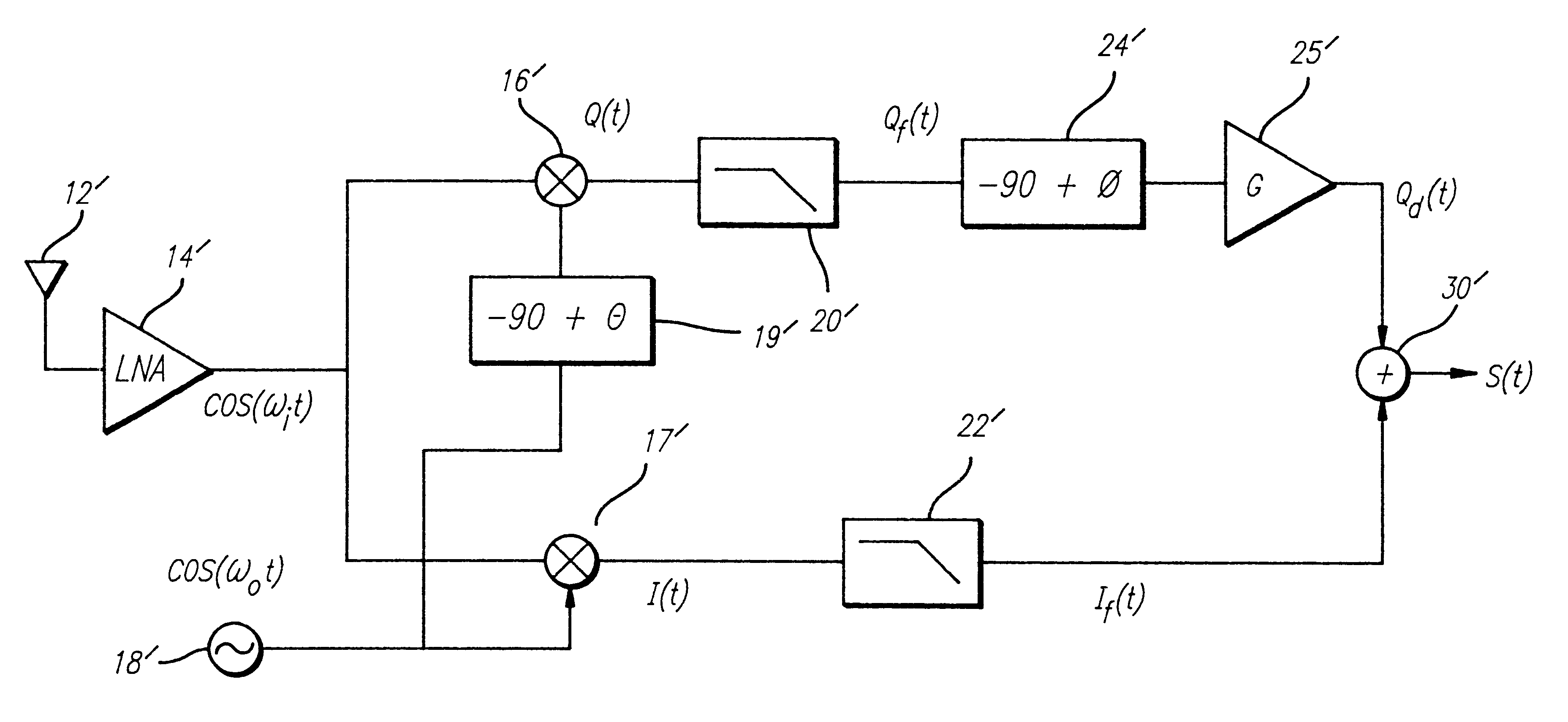
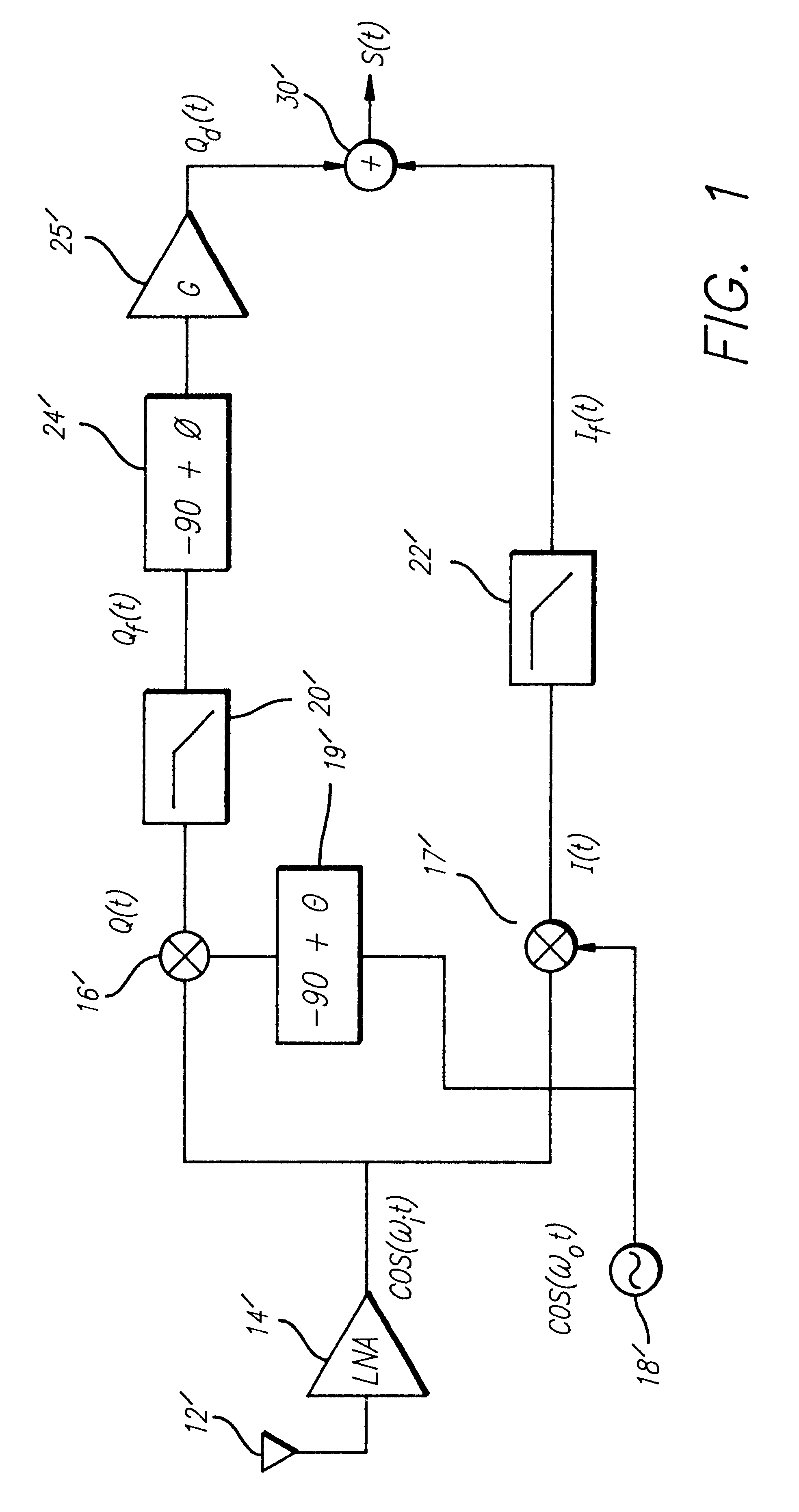
FIG. 1 is a block diagram of a typical conventional implementation of an image rejecting receiver. The receiver 10' includes an antenna 12' which provides a received signal to a Low Noise Amplifier (LNA) 14'. The LNA14' outputs an RF (radio frequency) signal to first and second mixers 16' and 17', respectively. A local oscillator 18' provides a reference signal ...


PUM


Abstract

A system and method for effecting wideband image rejection. In a receiver implementation, the inventive method includes the steps of receiving a first signal in a first frequency band and generating in-phase and quadrature signals therefrom. The phase of the in-phase signal is shifted to provide a second signal and the phase of the quadrature signal is shifted to provide a third signal. A predetermined phase relationship is thereby effected between the second and the third signals. The second and third signals are then summed to provide an output signal which has minimal interference from a mixing signal. In an illustrative receiver application, the phase shifting is achieved via the use of all pass networks. Each of the all pass networks include a differential amplifier having first and second input terminals. The first and the second terminals are connected to a first end of first and second resistive elements, respectively. The second ends of the first and second resistive elements are connected to a common input terminal for the network. The first input terminal is a negative terminal and is connected to an output terminal of the network. The second terminal is a positive terminal and is connected to a source of ground potential via a capacitive element.

Description

1. Field of the InventionThe present invention relates to communications systems. More specifically, the present invention relates to systems and techniques for receiving signals over a wide range while preventing interference from intermediate frequency (IF) images with desired signals.2. Description of the Related ArtReception of electromagnetic signals is effected by a transmission and reception of signals in a first relatively high frequency band (such as radio frequency or `RF`) and subsequent downconversion of the received signal to a lower frequency band (such as IF.) Downconversion is typically achieved by mixing the received signal with a reference signal generated by a local oscillator (LO). For example, an RF signal received at a frequency of 1000 kilohertz (kHz) might be mixed down to 100 kHz by a mixer having a 900 kHz reference signal from a local oscillator. Under these conditions, a signal at 800 kHz would have the same IF (intermediate frequency) and would therefore...

Claims


Application Information

Patent Timeline
Patent Type & Authority Patents(United States)
IPC IPC(8): H03D3/00H04L27/38H03D7/18H04B1/10H04B1/26H04L27/233
CPCH03D3/007
Inventor SPARGO, THOMAS A.LINDER, LLOYD F.GORDER, MATTHEW S.
Owner MICROELECTRONICS TECH INC
Why Eureka
Try Eureka