

Component for holding down measuring leads
a technology of measuring leads and components, applied in the direction of heat measurement, threaded fasteners, instruments, etc., can solve the problems of inability to avoid, high cost, and inevitable breakdown, and achieve the effect of higher coefficient of thermal expansion
Inactive Publication Date: 2003-10-28
ALSTOM TECH LTD
View PDF6 Cites 2 Cited by
- Summary
- Abstract
- Description
- Claims
- Application Information
AI Technical Summary
Benefits of technology
The solution is cost-effective, requires no special tools for installation, and ensures reliable retention of measuring leads across different operating conditions, with the austenitic steel disk expanding to maintain a tight fit within the ferritic material groove.
Problems solved by technology
Disadvantages with this solution are, on the one hand, the high costs which are caused by the requisite very exact flanks when milling the transverse groove and, on the other hand, inevitable breakdowns on account of the point-like contact, which can scarcely be avoided, of the heavy-duty spring dowel sleeve on the measuring lines or measuring devices.
However, these snap rings require an undercut groove for fitting and clamping, so that the cost of production is also relatively high with this solution.
A further disadvantage consists in the fact that the snap ring only has a small clamping force, which even decreases during operation of the gas turbine, so that the snap ring jumps away in a spring-loaded manner and can thus no longer perform its task as a hold-down.
Method used
View moreImage
Smart ImageViewing Examples

Examples
first embodiment
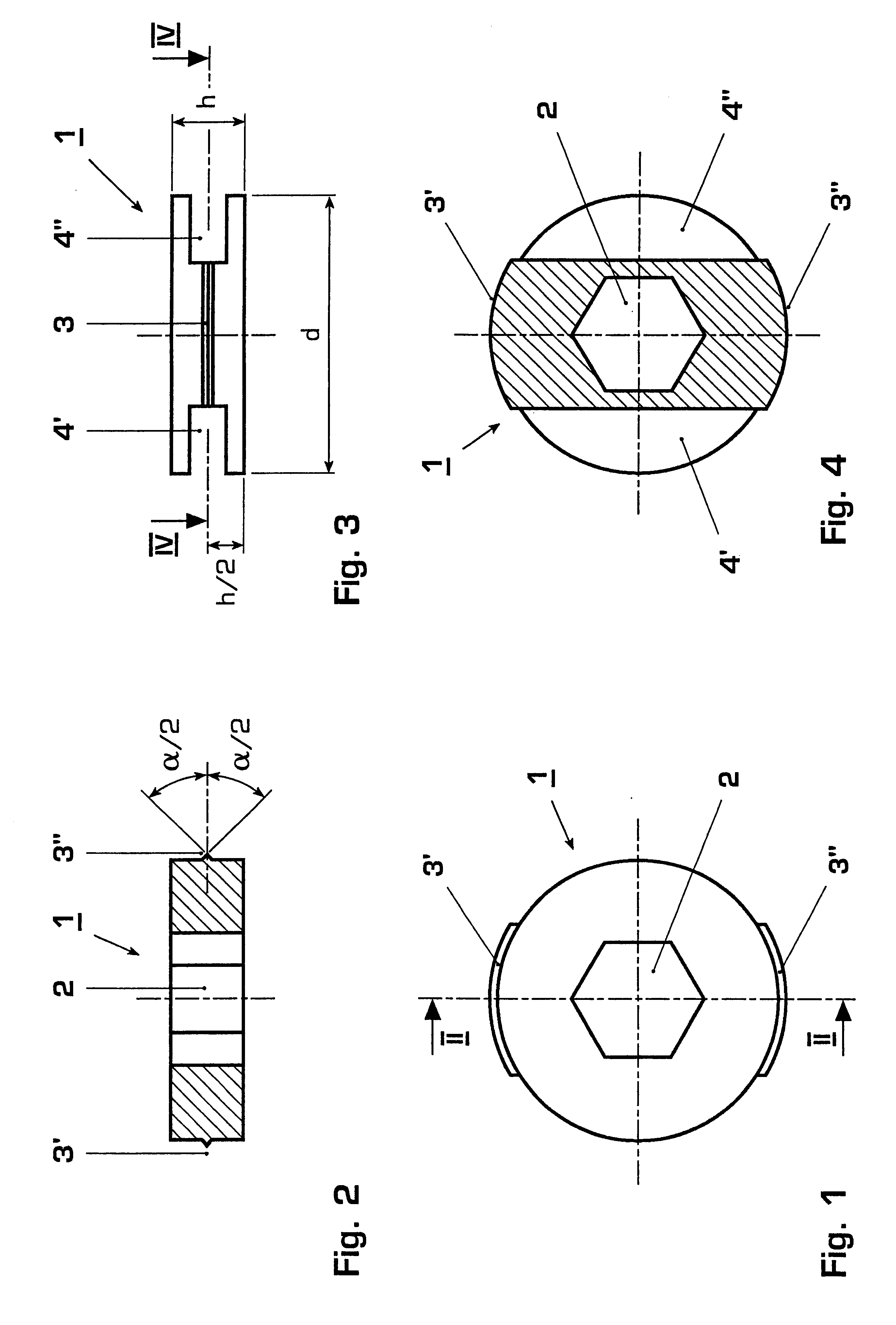
FIG. 1 shows a plan view of the component according to the invention in a first embodiment;
FIG. 2 shows a section through the component along line II--II in FIG. 1;
FIG. 3 shows a side view of the component according to FIG. 1;
FIG. 4 shows a section through the component along line IV--IV in FIG. 3;
second embodiment
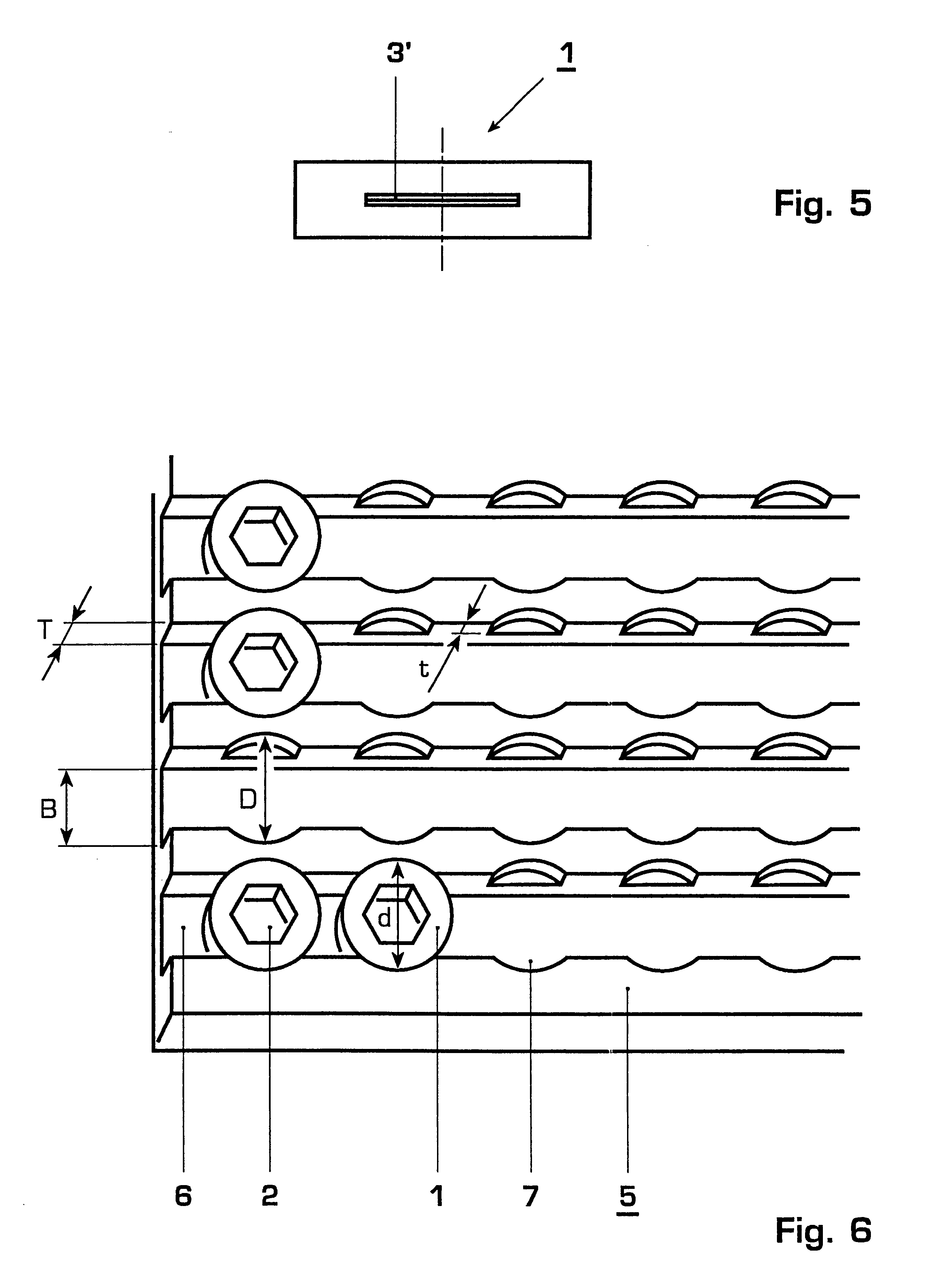
FIG. 5 shows a side view of the component according to the invention in a second embodiment;
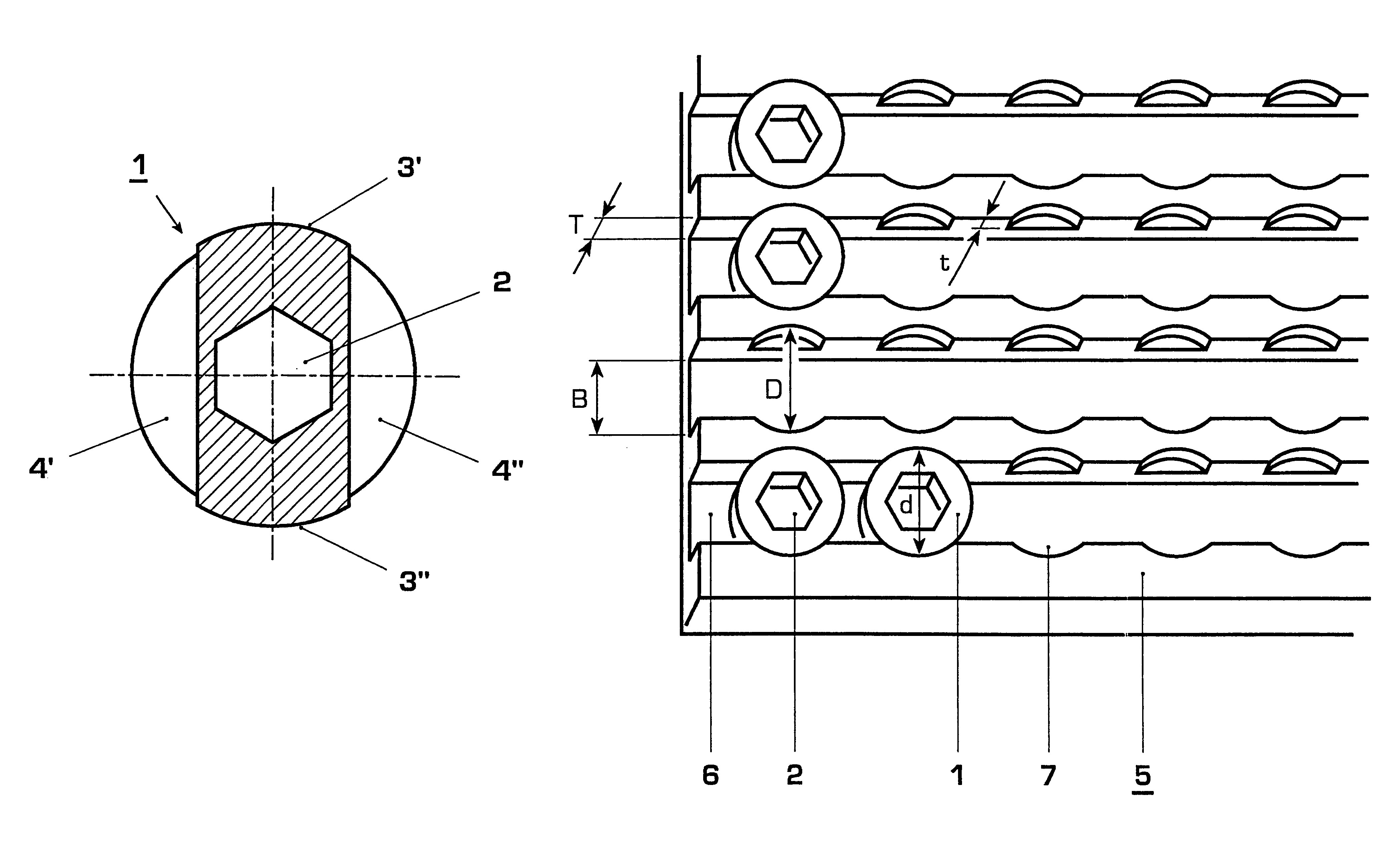
FIG. 6 shows a perspective representation of the component according to the invention fitted into the machine part.
Only the features essential for the invention are shown. The same elements have the same reference numerals in different figures.
Login to View More PUM
| Property | Measurement | Unit |
|---|---|---|
| flank angle | aaaaa | aaaaa |
| circumference | aaaaa | aaaaa |
| height | aaaaa | aaaaa |
Abstract
The invention relates to a component for holding down measuring leads and measuring devices in a groove (6), provided therefor and having holes (7), of a machine part (5). It is characterized in that the component is designed in the form of a disk (1) which has a cutting edge (3) on its circumference, the cutting edge (3) not being formed continuously over the entire circumference but consisting of two partial cutting edges (3', 3'') circumferentially opposite one another. In addition, the disk (1) has a central opening (2) in the form of a hexagon socket. For fitting, the disk (1) is put into the hole (7) in such a way that its two partial cutting edges (3', 3'') point in the longitudinal direction of the groove (6), then a hexagon socket key is inserted into the opening (2) of the disk (1) and the key is turned while the disk (1) is pressed down at the same time, so that the cutting edges (3', 3'') cut into the material of the machine part (5) and jam tight.
Description
The invention relates to a component for holding down measuring leads and measuring devices in a groove, provided therefor, of a machine part.PRIOR ARTIt is known to monitor machines, such as thermal turbomachines for example, during operation by means of special measuring devices in order to be able to quickly detect faults in the machine. On the one hand, it is thus possible, on account of manual or automatic corrections immediately carried out, to prevent damage to the machine in the operating state or, in the worst case, stoppage of the machine; on the other hand, such measurements provide for potential improvements to the machine by weak points being detected.The measuring leads are laid in grooves which are normally milled in the relevant machine parts. In order to ensure that the measuring leads remain in the grooves provided for them when they are fitted, special components--"hold-downs"--have to be used.For example, it is known to use a heavy-duty spring dowel sleeve as a h...
Claims
Login to View More Application Information
Patent Timeline
 Patent Type & AuthorityPatents(United States)
IPC IPC(8): F16B1/00G01K1/14F16B37/04F01D25/00F02C7/00F16B1/02F16B1/04F16B17/00F16L3/24
CPCF16B1/00G01K1/14F16B37/045Y10T403/18Y10T407/20Y10T29/49945
InventorBREHM, ARMINRADOVIK, GORANWETTER, HUGO
OwnerALSTOM TECH LTD