Golf club

a technology of golf clubs and golf balls, applied in golf clubs, sport equipment, golf, etc., can solve the problem that the proportions free of plating will naturally get rusty

Inactive Publication Date: 2003-10-28
ENDO MFG COMPANY
View PDF7 Cites 32 Cited by
  • Summary
  • Abstract
  • Description
  • Claims
  • Application Information

AI Technical Summary

Problems solved by technology

However, there would occur a problem that portions free from plating will naturally get rusty.

Method used


Image

  • Golf club
  • Golf club

Examples


Embodiment Construction

Hereinafter will be described an embodiment of the invention with reference to the attached drawings.

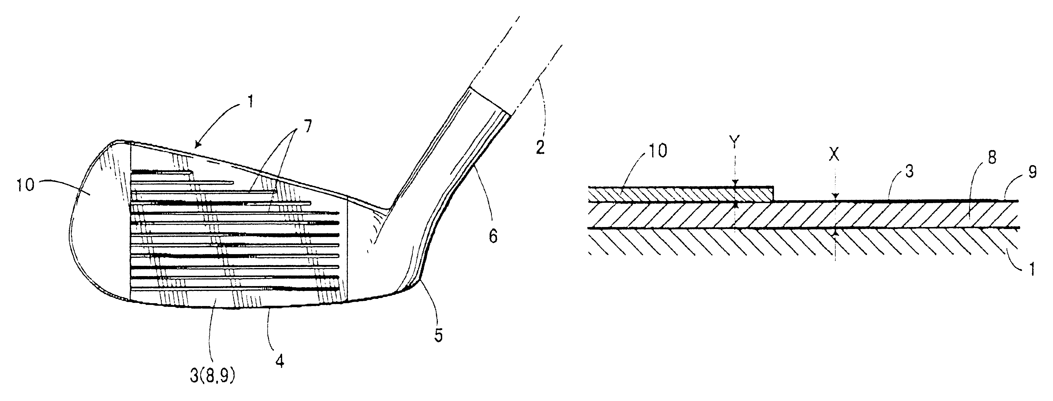
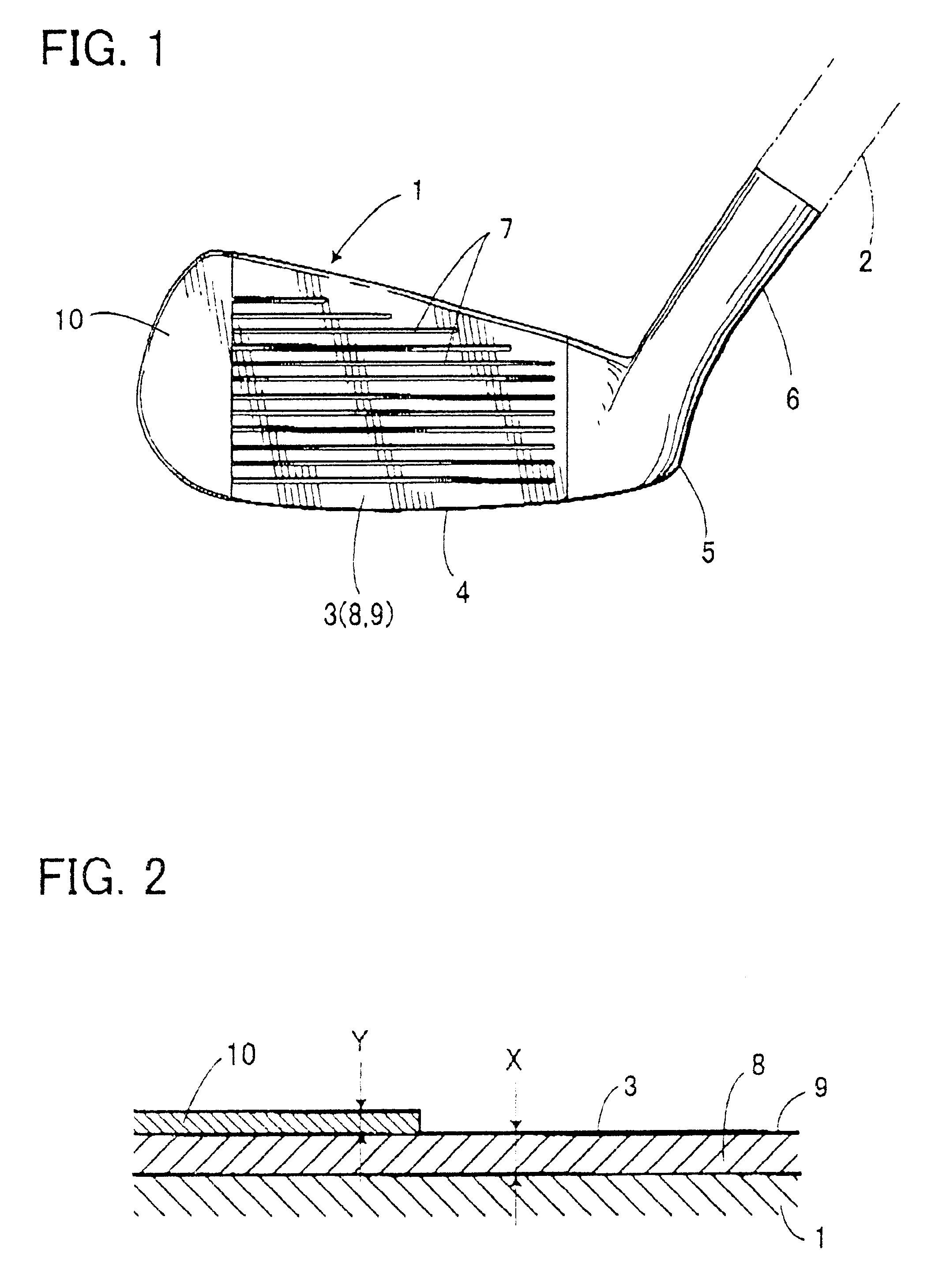
As shown in FIGS. 1 and 2, a golf club of the invention is of an iron type, constructed of a golf club head 1 and a shaft 2 provided above a first side thereof. The head 1 includes a face 3 formed in a front, a sole 4 in a bottom, a heel 5 formed in a lower portion of the said first side, said heel 5 being provided at the first side of said sole 4, and a hosel 6 formed above the heel 5 for connecting the shaft 2 thereto. In the meantime, reference numeral 7 in the drawings designates lateral grooves formed on the face 3, which are called score lines. The aforesaid face 3 is defined approximately between the right and left ends of the lateral grooves 7.

The metallic head 1 may be manufactured by suitable manufacturing methods. For example a round bar of S20C may be first processed by hot forging, and then may be machined and polished to a final product. Forming the head 1 by forging wo...


PUM


Abstract

A golf club which can give a golf player a soft feel of striking. A metallic head 1 has a face 3 whose surface is formed with a silver plating layer 8 of Hv 200 or below. Thus, the surface of the face 3 is protected from rust, and a softer feel of striking can be obtained when he strikes a ball, unlike conventional golf clubs with hard plating layer. As the surface for striking balls is comparatively soft, a period of time that a ball is contact with the face 3 is prolonged, thus making it easier for a player to give a spin to the ball. A black layer 9 is formed on the silver plated surface of the face 3, and thus less reflection of light is resulted at the time of addressing a ball, so that balls can be addressed easily.

Description

a) Field of the InventionThe present invention relates to a golf club.b) Prior ArtGolf clubs which comprise a head and a shaft, are generally classified as one of three types: a wood, an iron, or a putter. Irons are classified by the loft angle of their head. Irons with a small loft angle (for example, from 20 to 30 degrees) are called "long irons", while irons with a large loft angle (for example, from 40 to 50 degrees) are called "short irons". Normally, irons are numbered in ascending order from longest to shortest, for example, Nos. 1, 2, 3, 4, 5, 6, 7, 8, 9, PW (pitching wedge) and SW (sand wedge).In golf clubs, soft feel of string balls is preferred, and thus conventional golf clubs have used low-carbon steel or soft iron such as S20C as materials, of which the surface has been plated for protecting from corrosion. Such conventional plating has been comparatively hard, such as hard chromium (Vickers Hardness:Hv900), nickel boron plating (Hv800), and nickel plating (Hv450).As g...

Claims


Application Information

Patent Timeline
Patent Type & Authority Patents(United States)
IPC IPC(8): A63B53/04A63B102/32
CPCA63B53/04A63B53/047A63B2053/0416A63B2209/00A63B2053/0425A63B53/0425A63B53/0416A63B60/00
Inventor YOSHIDA, HIROYUKI
Owner ENDO MFG COMPANY
Why Eureka
Try Eureka