Broadcast receiver

a receiver and broadcast technology, applied in the field of broadcast receivers, can solve the problems of high realization cost, and achieve the effect of low realization cos

Inactive Publication Date: 2003-10-28
SONY INT (EURO) GMBH
View PDF12 Cites 62 Cited by
  • Summary
  • Abstract
  • Description
  • Claims
  • Application Information

AI Technical Summary

Benefits of technology

Therefore, it is the object underlying the present invention to provide a receiver for bro

Problems solved by technology

In these solutions, the AFC (Automatic Frequency Control) and the AGC (Automatic Gain Control) as well as the digital filtering of a compl

Method used


Image

  • Broadcast receiver
  • Broadcast receiver
  • Broadcast receiver

Examples


Embodiment Construction

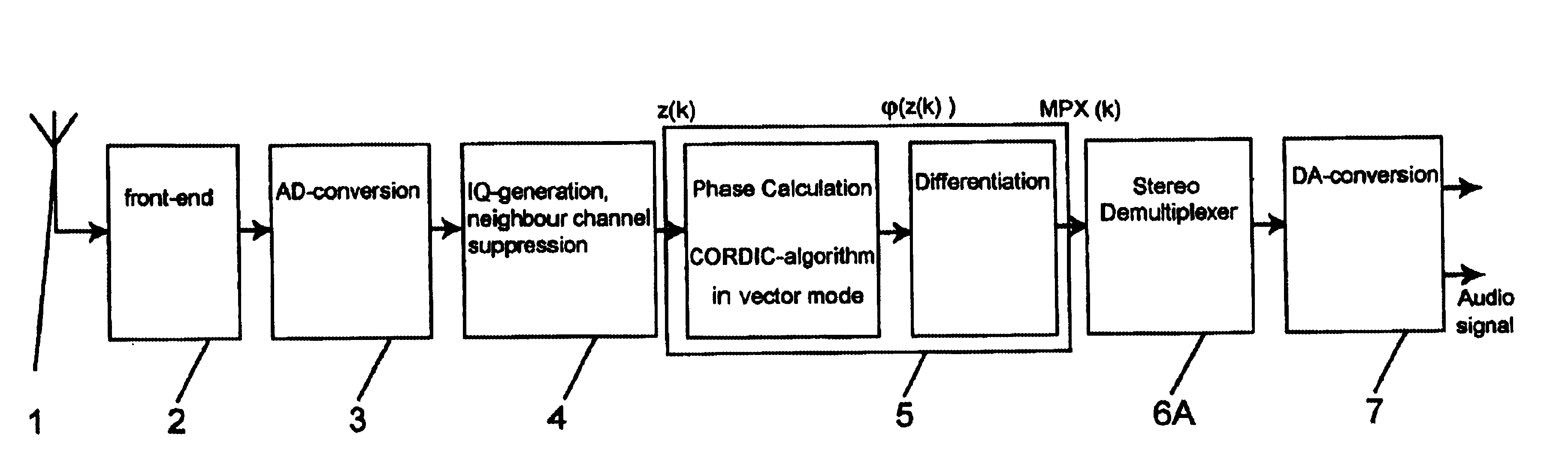
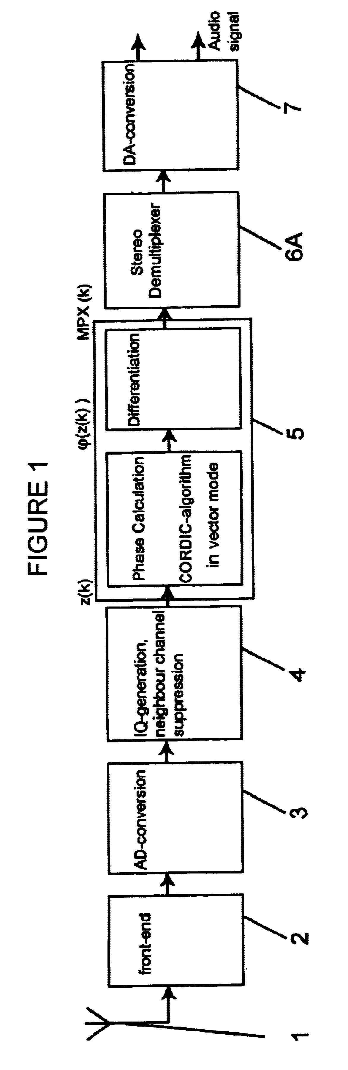
FIG. 1 shows the functionality of a receiver according to the present invention for mode A in which the polyfunctional circuit 5 performs a frequency demodulation. A FM broadcast signal is received with an antenna 1 and converted with a front-end block 2, an A / D converter 3 and an IQ generator 4 into a complex baseband signal z(k). This complex baseband signal z(k) might also undergo a neighbor channel suppression within the IQ generator 4 before it is fed to the polyfunctional circuit 5 according to the present invention that performs the digital frequency demodulation and outputs a digital multiplex stereo signal MPX(k) which gets demultiplexed by a stereo demultiplexer 6A before it gets converted into an analog audio signal by a D / A converter 7.

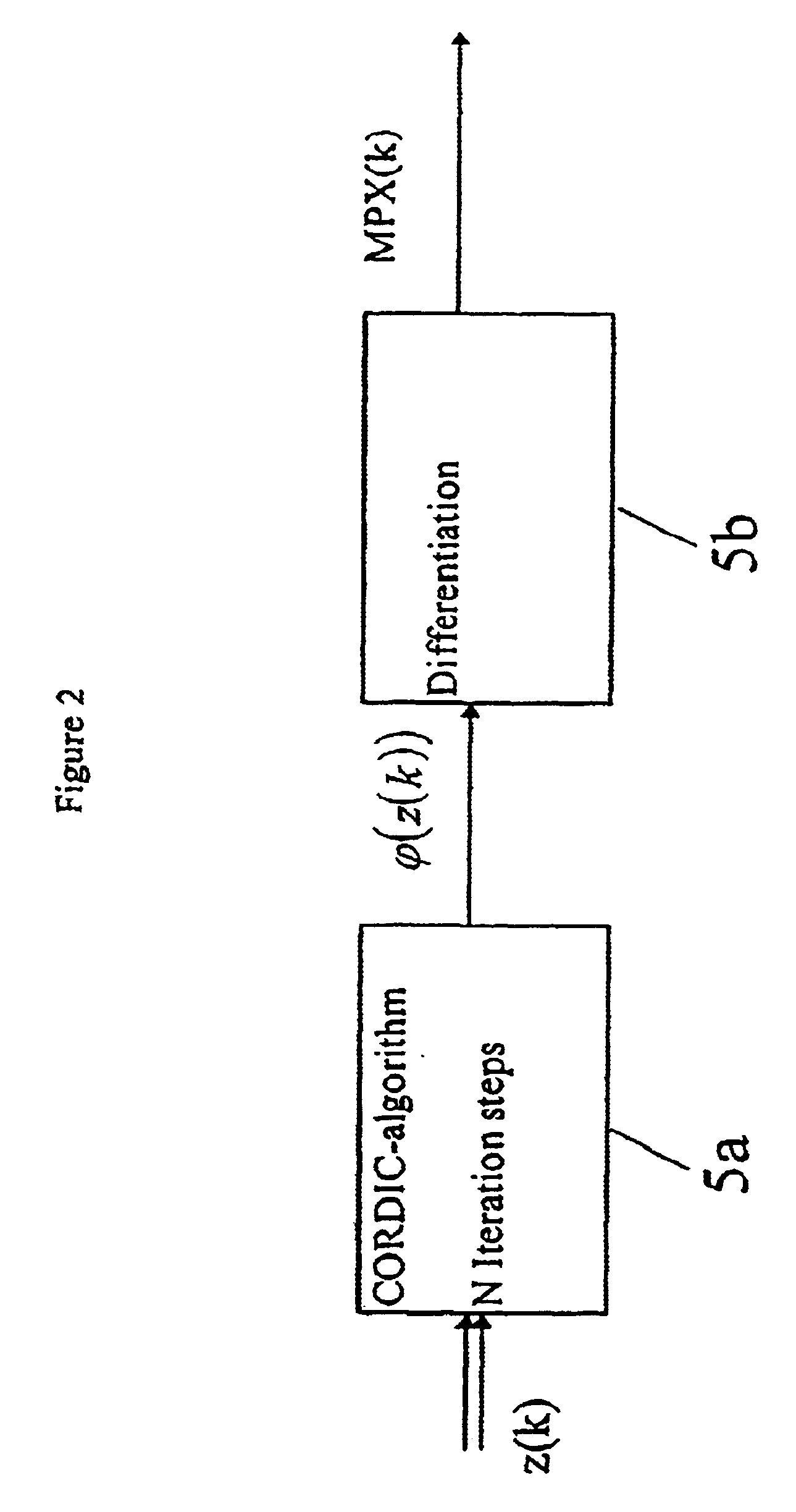
FIG. 2 shows that the frequency demodulation within the polyfunctional circuit 5 is done by a differentiation of the phase of the frequency modulated carrier. Therefore, according to the present invention, the phase value .phi.(z(k)) for e...


PUM


Abstract

A receiver for broadcast signals, e.g. DAB, FM, DVB, and digital or analog short-wave RF broadcast signals according to the present invention includes a polyfunctional circuit (5) that can be switched into three modes and performs the digital frequency demodulation which is needed for the reception of a frequency modulated signal in a first mode A, a digital frequency adjustment of the receiver in case of the reception of a digital or analog modulated broadcast signal like DAB, DVB, DRM or AM in a second mode B and the digital frequency adjustment and the digital gain control of the receiver which is needed in case of the reception of a digitally modulated broadcast signal like DAB, DVB, DRM in a third mode C. Depending on the needed functionality not all of these modes need to be realized. Nevertheless, the same hardware will be used for different purposes although the circuit is realized with an optimized amount of hardware to realize an efficient receiver.

Description

The present invention relates to a receiver for broadcast signals, e.g. DAB, FM, DVB, and digital or analog short-wave RF broadcast signals, e.g. DRM or AM signals, in particular to receivers for digitally modulated signals and / or multi-transmission system receivers for at least two different broadcast signals.BACKGROUND OF INVENTIONState of the art multi-transmission system receivers that can be switched between different RF broadcast signals usually comprise separate processing blocks each of which is directly related to a specific type of RF broadcast signal in-between the input stages of a RF receiver, like antenna, front-end block, A / D converter and IQ generator, and the output stage, like D / A converter. Such individual circuits respectively perform e.g. the digital frequency demodulation which is needed for the reception of a frequency modulated signal, the digital frequency adjustment of the receiver in case of reception of AM or short-wave broadcast signals and the digital f...

Claims


Application Information

Patent Timeline
IPC IPC(8): H04H1/00H04L27/00H03D1/00H03D3/00H04B1/06H04B1/16H04H40/18H04N5/44
CPCH04L27/0008H04H40/18H04N5/44
Inventor WILDHAGEN, JENS
Owner SONY INT (EURO) GMBH
Why Eureka
Try Eureka