
Magnetic transducer, thin film magnetic head, method of manufacturing magnetic transducer and method of manufacturing thin film magnetic head

a technology of magnetic transducers and magnetic heads, applied in the field of magnetic transducers and thin film magnetic heads, can solve problems such as field deterioration, resistance change, magnetic effect,

Inactive Publication Date: 2003-11-11
TDK CORPARATION
View PDF10 Cites 10 Cited by
  • Summary
  • Abstract
  • Description
  • Claims
  • Application Information

AI Technical Summary

Benefits of technology

This design enhances thermal stability and increases the exchange coupling magnetic field, leading to improved resistance change rates and reduced adverse influences from impurities, thereby improving the overall performance of the magnetic transducer and thin film magnetic head.

Problems solved by technology

However, the above-mentioned U.S. Pat. No. 5,828,529 gives no report about specific improvements in thermal stability.
When the average in-surface crystal particle diameter is less than 3 nm, there is a problem that a magnetoresistive effect (i.e., properties of resistance changing according to a change in a signal magnetic field) deteriorates.

Method used


Image

  • Magnetic transducer, thin film magnetic head, method of manufacturing magnetic transducer and method of manufacturing thin film magnetic head
  • Magnetic transducer, thin film magnetic head, method of manufacturing magnetic transducer and method of manufacturing thin film magnetic head
  • Magnetic transducer, thin film magnetic head, method of manufacturing magnetic transducer and method of manufacturing thin film magnetic head

Examples


examples 1 to 5

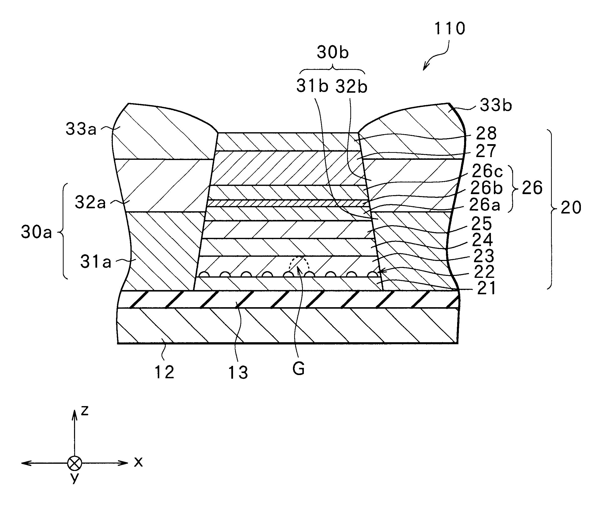
The stacks 20 shown in FIG. 7 were made as examples 1 to 5.

Each stack 20 was made in the following manner. First, in a vacuum chamber, the underlayer 21 of 3 nm thick was formed of Ta by means of sputtering on an insulating substrate made of Al.sub.2 O.sub.3 --TiC on which an Al.sub.2 O.sub.3 film was formed. Then, an O.sub.2 gas was introduced into the vacuum chamber so that the degree of vacuum in the vacuum chamber was 5.times.10.sup.-3 Pa, and thus O was absorbed on the surface of the underlayer 21, whereby the crystal-growth inhibitor layer 22 was formed. Then, the first soft magnetic layer 23 of 2 nm thick was formed of NiFe on the crystal-growth inhibitor layer 22, then the second soft magnetic layer 24 of 2 nm thick was formed of CoFe on the first soft magnetic layer 23, and then the nonmagnetic layer 25 of 2.1 nm thick was formed of Cu on the second soft magnetic layer 24. The inner ferromagnetic layer 26a of 3 nm thick was formed of CoFe on the nonmagnetic layer 25, then t...


PUM

PropertyMeasurementUnit
average crystal particle diameteraaaaaaaaaa

Abstract

Provided are a magnetic transducer and a thin film magnetic head having good thermal stability and capable of obtaining a high exchange coupling magnetic field, a method of manufacturing a magnetic transducer and a method of a manufacturing a thin film magnetic head. An MR element has a stack having a stacked structure comprising an underlayer, a crystal-growth inhibitor layer, a first soft magnetic layer, a second soft magnetic layer, a nonmagnetic layer, a ferromagnetic layer, an antiferromagnetic layer and a cap layer, which are stacked in sequence. The ferromagnetic layer has an inner ferromagnetic layer, a coupling layer and an outer ferromagnetic layer, which are stacked in this order on the nonmagnetic layer. The crystal-growth inhibitor layer inhibits crystal growth of the layers formed on the crystal-growth inhibitor layer, thereby limiting an average in-surface particle diameter of the inner ferromagnetic layer to within the range of from 3 nm to 8 nm inclusive, so that an interface between the coupling layer and the inner ferromagnetic layer becomes flattened.

Description

1. Field of the InventionThe invention relates to a magnetic transducer and a thin film magnetic head using the same. More particularly, the invention relates to a magnetic transducer capable of improving thermal stability and obtaining a high exchange coupling magnetic field, a thin film magnetic head using the same, a method of manufacturing a magnetic transducer and a method of a manufacturing a thin film magnetic head.2. Description of the Related ArtRecently, an improvement in performance of a thin film magnetic head has been sought in accordance with an increase in a surface recording density of a hard disk or the like. A composite thin film magnetic head, which has a stacked structure comprising a reproducing head having a magnetoresistive element (hereinafter referred to as an MR element) that is a type of magnetic transducer and a recording head having an inductive magnetic transducer, is widely used as the thin film magnetic head.MR elements include an AMR element using a ...

Claims


Application Information

Patent Timeline
Patent Type & Authority Patents(United States)
IPC IPC(8): G01R33/06G01R33/09H01F10/00H01F10/32G11B5/39G11B5/31H01F10/16H01F10/30H01F41/14H01L43/08H01L43/12
CPCB82Y10/00B82Y25/00G01R33/093G11B5/3903H01F10/324H01F10/3268G11B5/3909G11B5/3163Y10T29/49044G11B5/3967G11B2005/3996
Inventor SANO, MASASHIARAKI, SATORUTSUCHIYA, YOSHIHIROUESUGI, TAKUMI
Owner TDK CORPARATION
Learn More