Information encoding method and apparatus, information decoding method and apparatus and recording medium

Inactive Publication Date: 2003-11-11
SONY CORP
View PDF71 Cites 52 Cited by
  • Summary
  • Abstract
  • Description
  • Claims
  • Application Information

AI Technical Summary

Benefits of technology

It is therefore a principal object of the present invention to provide a method and apparatus for encoding, a method and apparatus for decoding and a reco

Problems solved by technology

This technique produces a flat quantization noise spectrum and minimizes the noise energy, but the noise level perceived by the listener is not optimum because the technique does not effectively exploit the psychoacoustic masking effect.
However, if the signal-to-noise ratio of such a system is measured using a strongly tonal signal, for example, a 1 kHz sine wave, non-optimum results are obtained because of the fixed allocation of

Method used


Image

  • Information encoding method and apparatus, information decoding method and apparatus and recording medium
  • Information encoding method and apparatus, information decoding method and apparatus and recording medium
  • Information encoding method and apparatus, information decoding method and apparatus and recording medium

Examples


Example

Referring to the drawings, preferred embodiments of the present invention will be explained in detail. In the following description, the parts or components similar to those of the conventional apparatus described above are omitted for clarity.

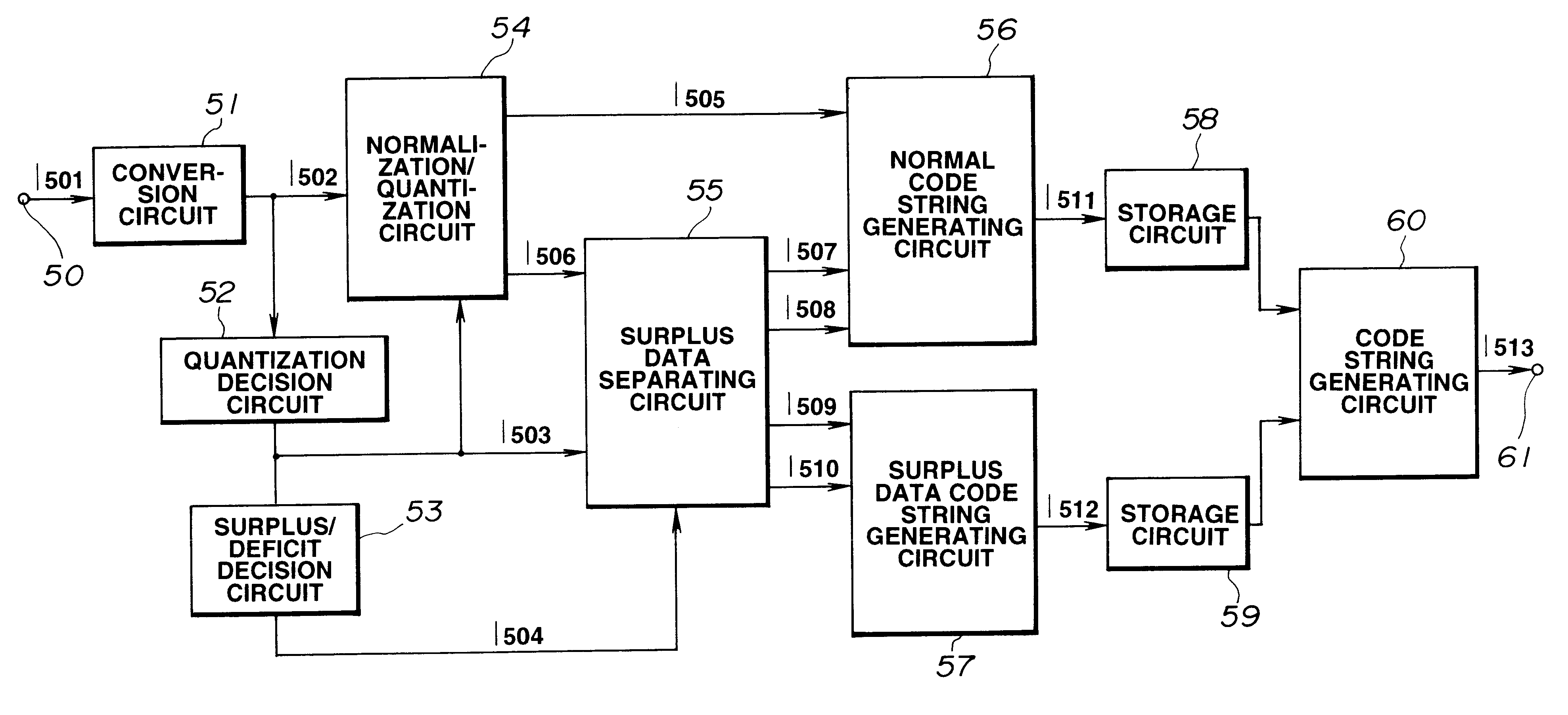
FIG. 9 shows a configuration of an encoder (encoding apparatus) for carrying out the encoding method for acoustic waveform signals according to the present invention.

The encoder according to an embodiment of the present invention has a quantization step decision circuit 52, a surplus / shortage decision circuit 53 and a surplus data separating circuit 55, for separating part of the encoding information for at least one second frame temporally consecutively or non-consecutively preceding or succeeding a first frame if such part is surplus data which would surpass a pre-set fixed number of bits for the second frame if the input signal for the second frame were encoded using the number of bits which would be required for realizing the required qual...


PUM


Abstract

A method of encoding information of an input signal using a fixed number of bits for each unit time frame. Part of the encoded information of at least one second frame temporally consecutively or non-consecutively preceding or following a first frame is contained in the encoded information of the first frame. This eliminates fluctuations in the sound quality due to bit surplus/shortage resulting from quantization for achieving efficient encoding and decoding.

Description

This invention relates to a method and apparatus for encoding input signals by high-efficiency encoding, a recording medium having the high efficiency encoded signals recorded thereon and a method and apparatus for decoding encoded signals transmitted over a transmission channel or reproduced from a recording medium to produce playback signals.There exist a variety of high efficiency encoding techniques of encoding audio or speech signals. Examples of these techniques include transform coding in which a frame of digital signals representing the audio signal on the time axis is pre-set time units or frames and the frame-based time-axis audio signals are converted by an orthogonal transform into a block of spectral coefficients representing the audio signal on the frequency axis, and a sub-band coding in which the frequency band of the audio signal is divided by a filter bank into a plurality of sub-bands without forming the signal into frames along the time axis prior to coding. Ther...

Claims


Application Information

Patent Timeline
IPC IPC(8): G10L19/00G10L19/02G10L19/035G11B20/10H03H17/00H03H17/02H03M7/30H04B14/04H04N19/00H04N19/115H04N19/18H04N19/423H04N19/46H04N19/625H04N19/63H04N19/70H04N19/85
CPCG10L19/035
Inventor OIKAWA, YOSHIAKI
Owner SONY CORP
Why Eureka
Try Eureka